Facebook
 Google
 GitHub
 Linkedin
Basic Amplifier Configurations: the Non-Inverting Amplifier
In previous videos, we explored the characteristics of an ideal operational amplifier, and then we introduced negative feedback as a technique that allows us to design high-performance amplifier circuits using nonideal real-life op-amps.
Amplifying with Op-Amps
Op-amps are versatile and can be incorporated into a wide variety of interesting and creative circuits. However, sometimes all we need to do is increase the amplitude of a signal, and for these applications, we have the basic op-amp non-inverting amplifier configuration. This simple topology consists of one op-amp and two resistors connected as follows:
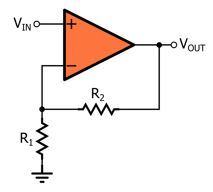
The Non-inverting Amplifier
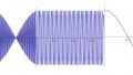
When we say that this circuit is “non-inverting,” we mean that it applies a positive gain to the input signal. If you connect a steady voltage to the input terminal, the output voltage will be equal to the input voltage multiplied by some number, with no change in polarity. If you apply a sinusoidal signal to the input terminal, the op-amp will increase the amplitude of the signal without creating a 180° phase difference.
Non-inverting operation is achieved by connecting the input signal to the op-amp’s non-inverting input terminal. The gain is determined almost completely by the two resistors, which form a feedback network connected between the op-amp’s output and its negative input terminal.
As you may recall from the video on negative feedback, the open-loop gain of the op-amp is not infinite, and therefore it does influence the closed-loop gain (GCL), but in practice the effect is small enough to be negligible. Thus, we can safely express the gain of the non-inverting amplifier as follows:

Input Impedance
When we are trying to transfer voltage from one subcircuit to another, the subcircuit that generates the signal should have low output impedance and the subcircuit that receives the signal should have high input impedance. One notable advantage of the non-inverting amplifier is that it has very high input impedance, because the input signal is connected directly to the op-amp’s input terminal. This is not the case with the inverting configuration, which is discussed in the next video tutorial.
Understanding the Non-inverting Amplifier
In the video on negative feedback, we learned that the closed-loop gain of a negative-feedback amplifier is approximately equal to the inverse of the feedback factor:

If you treat R1 and R2 as a resistive-divider feedback network, you can use this relationship between GCL and β to derive the expression for the gain of the non-inverting amplifier; this technique is briefly demonstrated in the tutorial on negative feedback. In this video, we’ll find the gain using typical circuit analysis.
-
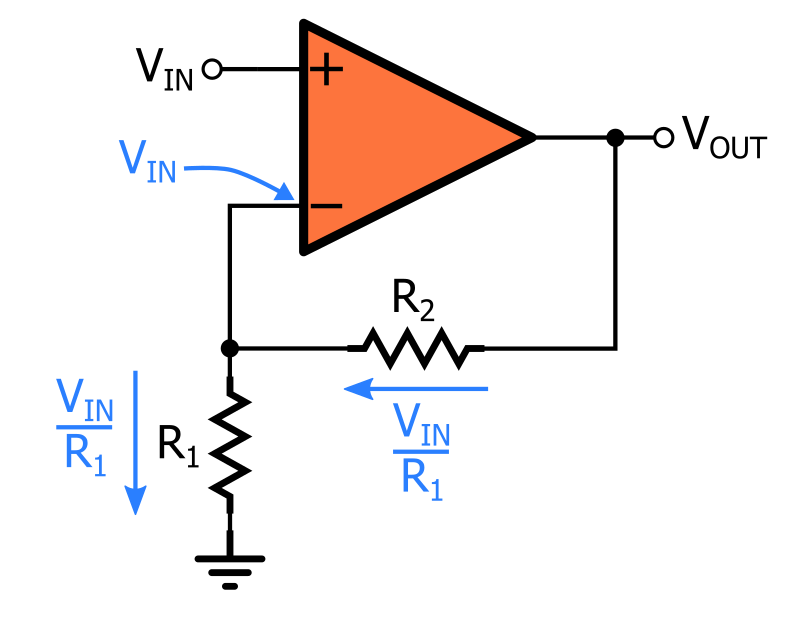
The input voltage VIN is applied to the non-inverting input terminal, and the virtual short assumption allows us to transfer this input voltage directly to the inverting input terminal.
-
VIN at the inverting input terminal generates a current of VIN/R1 flowing toward ground.
-
We assume that no current flows into or out of the op-amp’s input terminals, and consequently, the current flowing through R2 must be equal to the current flowing through R1: IR2 = VIN/R1. This current is flowing away from the op-amp’s output terminal.
-
The voltage drop across R2 is IR2 × R2 = (VINR2)/R1.
-
Since the lower-voltage terminal of R2 is connected to the inverting input terminal, the output voltage is equal to VIN plus the voltage across R2: VOUT = VIN + (VINR2)/R1 = VIN(1 + R2/R1).
Recap
- We can achieve non-inverting amplification by means of a simple circuit that requires only an operational amplifier and two resistors.
- The closed-loop gain is determined by the values of the two resistors.
- The non-inverting op-amp configuration has very high input impedance.
Related Content