 Facebook
 Google
 GitHub
 Linkedin
Basic Fundamentals of Lock-In Amplifiers
This article discusses the theory fundamentals of lock-in amplifiers.
Sometimes we find ourselves in need of measuring very, very low voltage signals—of the order of nanovolts or even smaller. We might think that it should not be a problem and take for granted such signals can be amplified using a traditional chain of operational amplifiers.
Well, we'd be wrong. Because we forgot about noise.
If a signal is amplified, so the accompanying noise. Therefore, even we amplify the desired signal, we will not be able to distinguish it from the background noise.
In this kind of situation, the solution is a lock-in amplifier. This article presents the theory on which they're based, as well as their main characteristics.
Lock-in Amplifiers and Noise
Imagine that you want to measure a 50 nV sinewave at 100 KHz. The frequency is not very high, so regular instruments such as an oscilloscope or a multimeter have enough bandwidth. On the other hand, the amplitude is quite low, so some amplification is of course needed.
Here, we can use a low noise amplifier (LNA) such as the AD8429, which has an input noise of 2 \(nV/\sqrt{Hz}\) and a bandwidth of 1.2 MHz with a gain of 100. Signal and noise at the output will be respectively:
\[s_{out}=s_{in}*G=50nV*100=5\mu V\]
\[n_{out}=n_{in}*G=2 \frac {nV}{\sqrt{Hz}}*\sqrt{1.2*10^6Hz}*100=219.089 \mu V\]
The noise is several times greater than the signal, making it impossible to properly measure the signal, even using an amplifier with good noise characteristics. Even if we add a high-Q filter before amplifying, which can be hard to achieve, the noise is still too high to recover the signal from the background noise.
We need a new solution—and its name is lock-in amplifier.
What is a homodyne receiver?
Before getting into the details, let's remind ourselves of a relatively old concept.
When a signal is sent through an antenna, it is never normally sent in its baseband, but modulated using a carrier signal. This carrier or reference signal can be from some KHz to several MHz, depending on the available technology, power consumption, and cost.
A homodyne receiver (and transmitter) uses only one frequency to move up and down the signal, as opposed to a heterodyne, which uses an intermediate frequency.
A basic homodyne receiver has the following aspect:
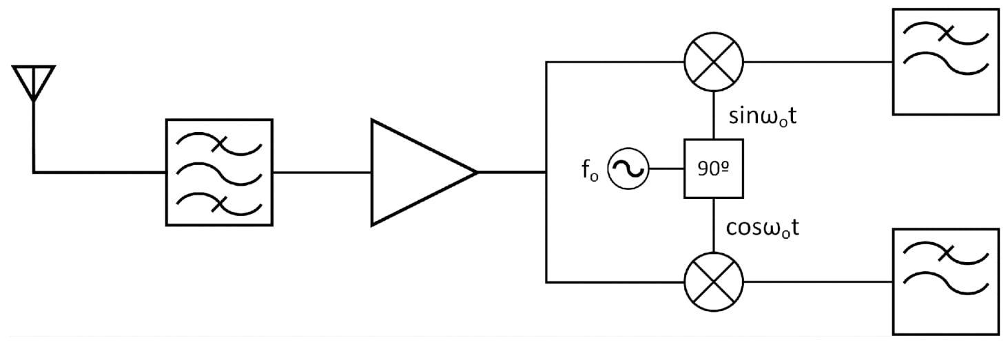
Figure 1. Schema of a homodyne receiver
The received signal is first filtered using a band-pass filter and then an amplifier with a low noise amplifier (LNA). A local oscillator generates a reference signal with a frequency fo. This signal is shifted 90º so the quadrature signal is generated.
This receiver is also known as an I/Q demodulator because it uses the components I (\(sin \omega _ot\)) and Q (\(cos \omega _ot\)).
At the final stage, each component is filtered out using a low pass filter.
Keep this concept in mind as we'll use it to understand lock-in amplifiers.
Time vs. Frequency Domains: Looking at Both Worlds
If the signal \(s(t)=A cos ( \omega_st)\), is sent using a homodyne transmitter, it is multiplied in the same way that it will be done in the receiver by the reference signal, as follows:
\[s(t)*s_c(t)=(\omega_st+\phi_1 *cos(\omega_ct+ \phi_2)= \frac {A}{2}(cos((\omega_s+ \omega_ct+ \phi_1+ \phi_2)+ cos((\omega_c- \omega_s)t+ \phi_2- \phi_1)))\]
Thus, multiplying two signals generates two new ones that are shifted, respectively at the frequency \(\omega_c + \omega_s\) and \(\omega_c - \omega_s\).
We can observe graphically the result at both time and frequency domains:
_low-frequency_signal.png)
Figure 2. s(t) is usually a low-frequency signal
_high-frequency_signal.png)
Figure 3. sc(t) is a precisely generated high-frequency signal
_and_fast_(modulated)_components_combined.png)
Figure 4. The combination of the slow component (envelope) and the fast component (modulated) can be clearly observed in the result
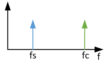
Figure 5. Sinusoidal signals are pure tones in the frequency domains
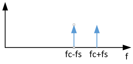
Figure 6. The frequency of a signal can be increased or decreased with a simple operation
One of the most relevant aspects is that the phase information becomes a function of \(\phi_1 \). Therefore, the quality of the phase at the reference signal will determine the quality of the recovered signal.
Lock-in Amplifier Principles
A basic lock-in amplifier is shown in Figure 7.
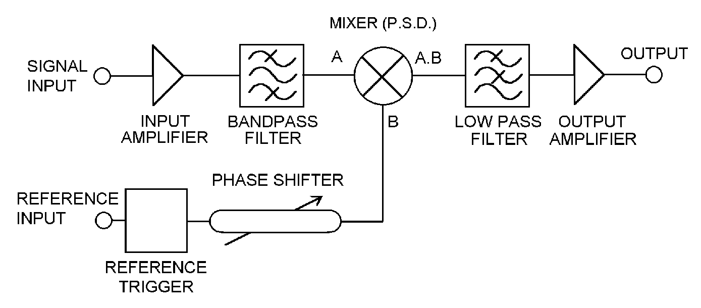
Figure 7. A basic lock-in amplifier. Image used courtesy of Signal Recovery
Does this seem familiar to you?
It is very similar to a homodyne receiver, with some subtle differences. The heart of the system is the phase shifter and the multiplier. This set-up guarantees that the signal at the output is coherent with the one we want to measure and that no other signal interferes with it.
Phase Sensitive Detection (PSD)
The multiplier block is also known as a mixer or phase-sensitive detector. This is because the output signal depends on the phase difference between the reference signal and the measured one.
In a regular situation, the reference signal frequency will be the same as the measured one—i.e., \(\omega_s= \omega_c \)—when multiplying both. The result will be:
\[s(t)*s_ct=\frac{A}{2}(cos( (2\omega_s)t+ \phi_1+\phi_2)+ cos(\phi_2-\phi_1)))\]
The result is a combination of two terms:
- A high-frequency signal at \(2f_s\) which will be filtered out and second
- A DC signal \(\frac{A}{2}cos \:cos(\phi_2+\phi_1)\) proportional to the phase shift between the reference signal and the desired one
Therefore, a lock-in amplifier will always yield a continuous signal.
Dynamic Reserve: How small can my signal be?
"Dynamic reserve" is a term used in lock-in amplifiers to define their ability to recover the signal from a determined noise level. Its regular definition is the ratio of the largest tolerable noise signal to the full-scale signal.
Dynamic reserve is usually expressed in a logarithmic scale (dB). For example, a dynamic reserve of 120 dB on a full scale of 1 µV means that noise can be as great as 1V without saturating the amplification chain.
It is important to note that the dynamic reserve depends on the selected full scale, otherwise a lock-in amplifier would have to be able to measure huge input signals when selecting big full-scale values.
Basic Lock-in Amplifier Review
I hope this article helped you achieve a better understanding of lock-in amplifiers and their uses. We can summarize our findings in the following points:
- Lock-in amplifiers, which are based on the concept of homodyne transceivers, can be the only solution when measuring very low voltages under the presence of a lot of noise.
- Lock-in amplifiers always provide a continuous signal proportional to the phase shift between the measured signal and the reference one.
- The quality of the reference signal determines the success of the signal detection
Related Content


