Facebook
 Google
 GitHub
 Linkedin
Basic Amplifier Configurations: the Inverting Amplifier
Signal Inversion
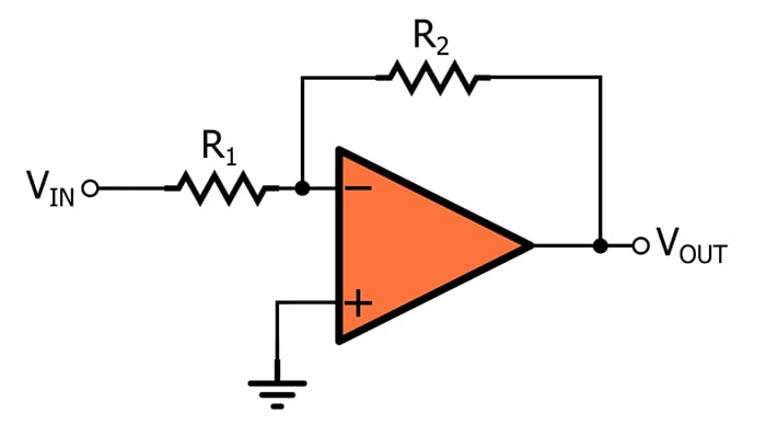
We learned in a previous video that the op-amp’s inverting input terminal provides a convenient means of implementing negative feedback. However, we can also use this terminal to create an amplifier that simultaneously amplifies and inverts the input signal. Here is the circuit:
Inversion corresponds to a negative closed-loop gain (for example, GCL = –10). Since VOUT = VIN × GCL, a negative gain will cause a positive input voltage to become a negative output voltage and a negative input voltage to become a positive output voltage.
With regard to electrical signals, an inverting amplifier produces a waveform that is reflected across the horizontal axis. The examples below convey the effect of inversion on a noisy DC voltage (the left-hand plot) and a sinusoidal signal (the right-hand plot).

When we are working with sinusoidal signals, inversion can be described in terms of phase shift. If we gradually shift an output sinusoid relative to an input sinusoid, we will eventually have an output signal whose minimum value coincides with the maximum value of the input signal. Thus, inverting a sinusoid effectively creates 180° of phase shift.
Why We Use the Inverting Configuration
The more intuitive approach to amplification is a non-inverting circuit. If the goal is simply to apply gain, why would we want to modify the signal’s polarity?
In some cases, inversion itself is desirable. For example, if a small negative voltage must be digitized by an analog-to-digital converter that cannot process signals that extend below ground, the op-amp inverting configuration would amplify the signal and establish proper polarity.
In other cases, inversion is not required, but it also is not problematic, and we use the inverting amplifier because it offers performance or functionality that is not available from the non-inverting amplifier. For example, the inverting configuration can reduce signal distortion, and it allows you to attenuate a signal (with the non-inverting configuration, the minimum gain is unity).
Understanding the Inverting Amplifier
As with the non-inverting amplifier, we can use standard circuit analysis techniques to determine the relationship between the input voltage and the output voltage of an op-amp inverting amplifier.
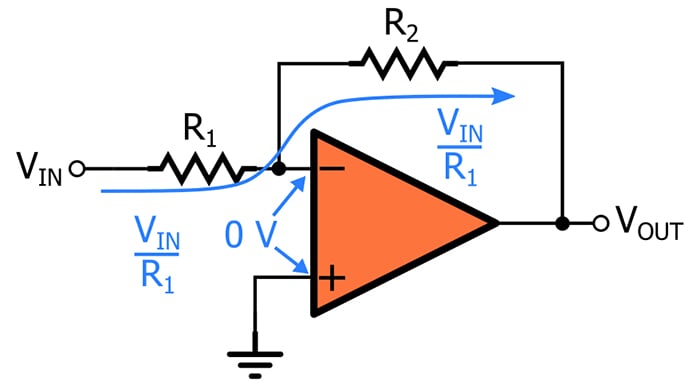
- The non-inverting input terminal is connected directly to ground. This means that we have 0 V at the non-inverting terminal and at the inverting terminal. (If this statement is a bit confusing for you, please take a look at AAC’s article on the virtual short assumption.)
- VIN is applied to R1 and generates a current of VIN/R1 flowing toward the inverting input terminal.
- Since we assume that current cannot flow into the input terminal, all that current travels around the op-amp and flows to the output node through R2. The voltage drop across R2 will be VINR2/R1.
- The left side of R2 is at 0 V, and since current is flowing from left to right, the voltage on the right side of R2 must be lower than the voltage on the left side. Thus, the voltage at the output node will be 0 V minus the voltage drop across R2: VOUT = 0 – VINR2/R1.
Based on this analysis, we can express the closed-loop gain (GCL) of the inverting configuration as follows:
\[\frac {V_{OUT}}{V_{IN}} = G_{CL} = - \frac {R_2}{R_1}\]
Note that this differs from GCL of the non-inverting configuration in two ways. First is the negative sign, which reflects the fact that the gain is always negative (because the ratio of the two resistances will always be positive). Second, GCL for the inverting expression does not have the “1 +” term, and this indicates (as mentioned above) that the gain of an op-amp inverting amplifier can be less than unity.
Recap
- The op-amp inverting configuration, like the non-inverting configuration, requires only one operational amplifier and two resistors.
- The inverting configuration creates a negative gain, meaning that one circuit can both amplify a signal and change its polarity from positive to negative or negative to positive.
- The magnitude of the gain is determined by the ratio between the two resistance values.
Related Content