 Facebook
 Google
 GitHub
 Linkedin
Non-inverting Configuration of an Operational Amplifier
Mentioned in the previous article, the first of two most commonly used operational amplifiers, the inverting configuration is heavily used in audio mixers or digital-to-audio converters. In this article, we will discuss the second amplifier configuration, known as the non-inverting amplifier.
Learn about non-inverting amplifiers.
Mentioned in the previous article, the first of two most commonly used operational amplifiers, the inverting configuration is heavily used in audio mixers or digital-to-audio converters. In this article, we will discuss the second amplifier configuration, known as the non-inverting amplifier.
Previous Article
The Inverting Configuration of an Amplifier
Non-inverting Configuration
The second closed-loop configuration of an operational amplifier that we'll be talking about in this series of articles is that of a Non-inverting Operational Amplifier and is shown in Fig. 1. In this configuration, the input signal v1 is applied right into the positive terminal (or non-inverting terminal) of the operational amplifier and at the negative terminal (or inverting terminal), a resistor R1 is connected to ground. This means that the output gain of the operational amplifier is changed to "positive" in value; on the other hand in the inverting amplifier, we saw that the output gain is negative in value. From this, we see that this will result in the output signal being in phase with the input signal.
Closed-Loop Gain
By analyzing the non-inverting circuit, we can determine its closed-loop gain (v0/v1) and is illustrated in Figure 1.2. The order of operation and procedure is labeled by boxed numbers on the figure. Suppose that the operational amplifier is considered to be ideal with an infinite gain, we see that there is a "virtual short circuit" that exists between the inverting and non-inverting input terminals. The difference in the input signal can be noted as
$$v_{id} = \frac{v_{0}}{A}=0$$ for $$A = \infty $$
Put into words, at the inverting input terminal, the voltage will be equivalent to the voltage value that is currently at the non-inverting input terminal, known as the applied voltage v1. A current that flows through R1 can thus be described as v1/R1. Due to the fact that the (ideal) operational amplifier has an infinite input impedance, the current through R1 will flow through R2 as well. We can now calculate for the output voltage from
$$v_{0} = v_{1} + \left ( \frac{v_{1}}{R_{1}} \right )R_{2}$$
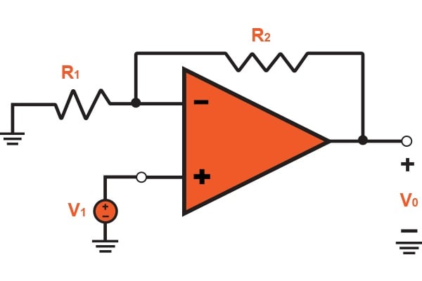
FIGURE 1.1: Noninverting Configuration
Which provides
$$\frac{v_{0}}{v_{1}} = 1 + \frac{R_{1}}{R_{2}}$$ (Eq. 1.1)
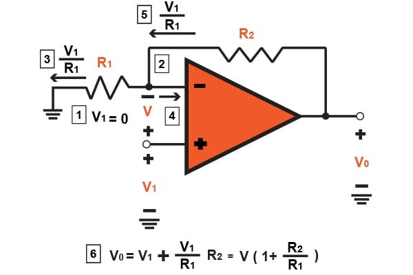
FIGURE 1.2
Also, by inspecting the non-inverting configuration further we can see how it operates. Because of the current that flows directly into the operational amplifier's inverting terminal is zero, the two resistors R1 and R2 act as a voltage divider that allows a small portion of the output voltage to loop back to the inverting input terminal. This is written by
$$v_{1}=v_{0}\left ( \frac{R_{1}}{R_{1}+R_{2}} \right )$$ (Eq 1.2)
Thus, the infinite gain and the "virtual short circuit" produced that is located between the inverting and non-inverting terminals of the operational amplifier will force the voltage to be equivalent to the voltage applied at the non-inverting input terminal. Then,
$$v_{0}\left ( \frac{R_{1}}{R_{1}+R_{2}} \right )=v_{1}$$
Which provides the operational amplifier's gain expression in equation 1.1.
We will stop to notice the presence and the action of the negative feedback that arises in the non-inverting configuration of Fig 1.1. By letting v1 increase, vid will increase consequently, and v0 will correspondingly increase due to the high gain of the (ideal) operational amplifier. However, when v0 is correspondingly increased, a small fraction is fed back into the inverting input terminal through the two resistors (or voltage divider). This feedback's purpose is to counteract the voltage increase in vid, and push it down to zero, although it is a higher value of v0 that does indeed correspond to the increase in v1. This is what is known as a degenerative action, thus, the feedback is given the name of degenerative feedback.
Finite Open-Loop Gain Effects
Just as was done for the inverting configuration, we will now take a look at the effects of the finite operational amplifier open-loop gain A on this configuration. By assuming the operational amplifier to be all ideal expect for the open-loop gain A, we can show that the closed-loop gain of the non-inverting configuration by
$$G=\frac{v_{0}}{v_{1}}=\frac{1+(R_{2}/R_{1})}{1+\frac{1+(R_{2}/R_{1})}{A}}$$ (Eq. 1.3)
It is of importance that for both configurations, inverting and non-inverting, the denominator of Eq. 1.3 is identical. This is because of the fact that both the configurations have the same exact feedback loop, which can easily be seen if the input signal source is short-circuited. It is only the denominators that are identical because the numerators give the ideal closed-loop gain (-R2/R1 for inverting and 1 + R2/R1 for non-inverting). One more thing to note is that the gain expression in Eq. 1.3 can be simplified and thus give the ideal value for $$A = \infty $$
Resistance
The gain A of this configuration is positive, hence, why it is called non-inverting. Looking at the input, the impedance of the closed-loop amplifier is ideally infinite, due to no current flowing into the noninverting input terminal of the operational amplifier. Now, looking at the other end, the output is to be taken at the terminals of the voltage source $$A(v_{2}-v_{1})$$, thus leaving the output resistance of the non-inverting configuration to be zero.
Voltage Follower
The high input impedance has a property that plays a key role of the noninverting configuration. This impedance allows the circuit to be used as a buffer amplifier that connects to a source that goes from a high to low impedance load. In many instances, the applications that use buffer amplifiers are not required to provide any voltage gain. Rather, it is used as an impedance transformer or a power amplifier instead. In these applications R2=0 and $$R_{1}=\infty $$ to provide for the unity-gain amplifier shown in Fig 1.3 (a). This circuit is commonly known as the voltage follower. This is known as a follower as the output follows the input's voltage. Speaking of the ideal case, v0=v1, $$R_{in}=\infty $$, $$R_{out}=0$$, and the circuit is shown in Fig 1.3 (b).
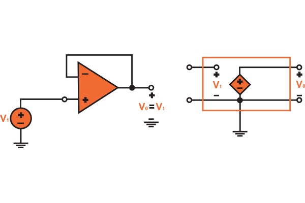
FIGURE 1.3 (a) (b)
Due to the fact that the voltage follower circuit's entire output is fed back directly into inverting input, the circuit is now said to have 100% negative feedback. The infinite gain of the ideal operational amplifier will now act to ensure that vid=0 and thus v0=v1.
Conclusion
To conclude this article, the non-inverting configuration has been discussed and explained. I hope that you have gained a better understanding of the purpose of this amplifier as well as how it is operated. Whether it is a buffer amplifier or impedance transformer, you'll find a non-inverting amplifier within it. Two things are to be remembered when discussing non-inverting amplifiers: no current flows through the noninverting input terminal and that the input signal is applied to the non-inverting terminal. From these two rules, we derived an equation to calculate the closed-loop gain of the non-inverting amplifier. If you have any questions or comments, please leave them below!
Related Content


Hello.. please is it possible to solve the following equation using one or more op-amp. thanks.
Y= -32.8ln(X) + 55.984 where Y is the output voltage value and X is the input voltage value