 Facebook
 Google
 GitHub
 Linkedin
Review of the Op-Amp Integrator
It is no surprise that an operational amplifier can provide amplification, but in the previous videos, we have seen that these versatile components can also be used to improve impedance relationships, convert a current signal to a voltage signal, and accurately rectify low-amplitude AC waveforms.
A particularly interesting application of op-amps is the realization of mathematical operations that might initially seem too complex to be implemented in a simple electronic circuit. In this video, we will learn about the op-amp integrator, which performs mathematical integration and requires nothing more than an op-amp and a few passive components.
The Theoretical Op-Amp Integrator
As shown in the diagram below, integration can be accomplished by using a typical inverting op-amp configuration, but with a capacitor in the feedback path instead of a resistor.
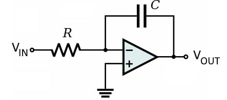
There are four key points that we need to understand in order to explain the behavior of the op-amp integrator:
- The virtual short ensures that the voltage at the inverting input terminal is always 0 V.
- Since the inverting input terminal is always at ground, the current flowing toward the inverting input terminal depends only on the input voltage and the input resistance (R).
- We assume that no current flows into the op-amp’s input terminals, and this means that the current flowing through the input resistance is equal to the current flowing through the feedback capacitor.
- The voltage (as a function of time) across the terminals of a capacitor is proportional to the integral (with respect to time) of the current flowing through the capacitor.
If we recall that one of the capacitor’s terminals is connected to ground through the virtual short, we can see that the magnitude of the output voltage will be equal to the magnitude of the voltage across the capacitor. Thus, the output voltage is proportional to the integral of the input current, and the input current is proportional to the input voltage. This means that the overall circuit produces an output voltage that is proportional to the integral of the input voltage.
The Integrator’s Transfer Function
The following diagram illustrates some of the statements made in the previous section, and it will help us to determine the exact relationship between an input voltage and an integrator’s output voltage.
![]()
The time-domain relationship between capacitor current and capacitor voltage is written as follows:
\[V_{C} = \frac{1}{C} \int I_c \: dt\]
The current flowing through the capacitor is equal to the input voltage divided by the resistance R, which means that we can express the capacitor voltage as
\[V_{C} = \frac{1}{C} \int \frac{V_{IN}}{R} \: dt\]
The resistance R is constant, so we can take it outside the integral, which leads to
\[V_{C} = \frac{1}{CR} \int V_{IN} \: dt\]
We can see from the polarity markings in the above diagram that the output voltage is equal to the capacitor voltage in magnitude but opposite in sign; thus,
\[V_{OUT}(t) = -\frac{1}{CR} \int V_{IN}(t) \: dt\]
If we translate this equation into words, we can say that the output voltage of the op-amp integrator is proportional to the negative integral of the input voltage, and the constant of proportionality is the feedback capacitance multiplied by the input resistance.
Preventing Saturation
The capacitor in the integrator’s feedback path is like any other capacitor—its voltage gradually increases as it stores charge delivered by current flow. If the input to the integrator is a constant DC voltage, a constant current will flow through the resistor and into the capacitor, and the capacitor’s voltage will increase until the op-amp reaches saturation.
This is expected behavior and is consistent with mathematical integration, though integration eventually must cease because the op-amp cannot produce an output voltage that exceeds the supply voltage. However, it turns out that the integrator circuit shown above will eventually saturate even when the input is shorted to ground!
This problem is caused by two nonideal aspects of real-life operational amplifiers, namely, offset voltage and input bias currents. The offset voltage creates a small but steady DC current through the feedback capacitor, and input bias currents lead to a DC input offset current that flows through the capacitor. Any DC current flowing in the feedback path will create a capacitor voltage that gradually increases toward saturation.
The diagram below shows the solution to this problem.
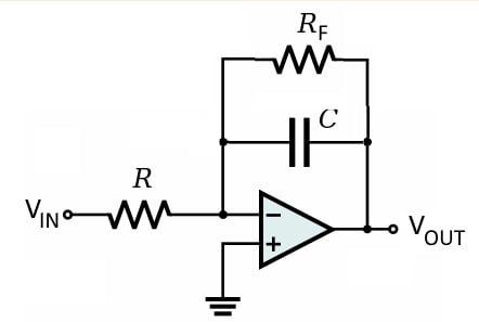
By adding a resistor in parallel with the feedback capacitor, we provide a consistent path for the DC currents discussed above. This is a simple and effective solution, but it comes with two side effects.
- The DC currents will create a small voltage drop across the feedback resistor. This is much better than a gradually increasing capacitor voltage, but it adds an undesirable error component to the output voltage.
- The feedback resistor affects the frequency response of the circuit, in such a way that the integrator becomes less mathematically ideal.
Unfortunately, these two side effects react in opposing ways to the value of the feedback resistor. A smaller feedback resistance generates lower DC error voltage but greater degradation of the frequency response, and a larger feedback resistance generates more DC error voltage but less frequency-response degradation.
Summary
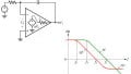
- An op-amp integrator performs mathematical integration. It can convert a square wave to a triangle wave, a triangle wave to a sine wave, or a sine wave to a cosine wave.
- The amplitude of the output signal is influenced by the resistance of the input resistor and the capacitance of the feedback capacitor.
- A theoretical integrator requires only one resistor and one capacitor, but real-life integrators must provide a resistive path for DC error currents. This is accomplished by adding a feedback resistor in parallel with the feedback capacitor.


Nice