 Facebook
 Google
 GitHub
 Linkedin
Op-Amp Basics: Introduction to the Operational Amplifier
Engineers currently have access to thousands of different op-amp ICs. It is somewhat misleading to identify all of these devices using the term “operational amplifier,” because in reality they form a diverse group of components. On the other hand, op-amps consistently exhibit various fundamental characteristics, and in this way they represent a fairly unified component category.
Why Do We Use Op-Amps?
Before we begin exploring the defining electrical characteristics of op-amps, we need to understand why these components are so popular and effective.
- Op-amps have been produced in large quantities for decades, and consequently engineers have access to a large and diverse collection of parts that offer both low cost and high performance.
- Operational amplifiers are extremely versatile. It is difficult to think of an analog circuit that cannot be either implemented using an op-amp or improved by the addition of an op-amp.
- Designing circuits around op-amps is much easier than using discrete transistors. The electrical characteristics of operational amplifiers lead to simplifying assumptions, and in many applications, these assumptions do not introduce significant differences between the theoretical circuit and the actual circuit.
The Op-Amp Circuit Symbol
The simplified, idealized op-amp is a three-terminal device.
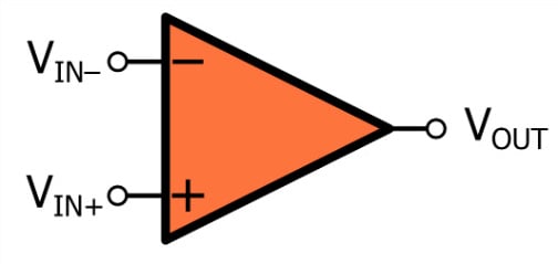
The two terminals on the left are inputs, and the terminal on the right is the output. Note that the input terminals have different labels: the plus sign indicates the non-inverting input terminal, and the minus sign indicates the inverting input terminal.
A real op-amp needs at least five terminals—two inputs, one output, and two power-supply connections:
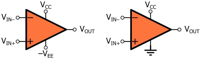
A dual-supply op-amp circuit (on the left) uses a positive supply voltage and a negative supply voltage. In a single-supply configuration (on the right), the negative supply terminal is connected to ground.
We often omit the power-supply terminals when we draw an op-amp because we assume that the device is connected to supply voltages that enable proper operation within the context of a given application. However, it’s important to remember that the op-amp’s output-voltage range is limited by its supply voltages.
The Op-Amp Electrical Model
The idealized input-to-output relationship of a typical op-amp is conveyed by the following diagram:
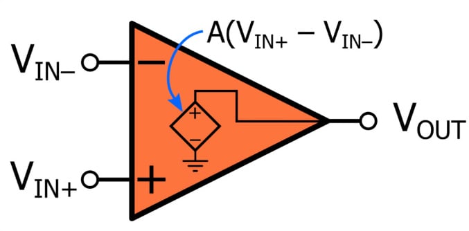
Despite the complex circuitry that is present within a real operational amplifier, we can successfully carry out many op-amp-based design tasks by assuming that the op-amp is a voltage-controlled voltage source (VCVS). The controlling voltage is \[(V_{IN+} - V_{IN-})\], and the factor of proportionality between the controlling voltage and the voltage generated by the VCVS is the op-amp’s gain, denoted by A:
\[V_{OUT} = A(V_{IN+}-V_{IN-})\]
Op-amps have very high gain, often above \[10^5\] or even \[10^6\] . As we’ll see in a future video, this high (ideally infinite) gain is extremely important—not because we frequently need to increase the amplitude of a signal by five or six orders of magnitude, but because an amplifier that combines high gain with a differential input stage provides a convenient means of exploiting the beneficial properties associated with negative feedback.
Let’s look at a few additional characteristics that are implied by the VCVS model shown above.
- An op-amp is a differential amplifier: it amplifies the difference between the two input voltages.
- It follows from the previous statement that op-amps exhibit common-mode rejection. The op-amp will reject (i.e., ignore) any voltage component, such as noise or a DC offset, that is present in both input signals.
- An op-amp has a differential input stage and a single-ended output; thus, it can be considered a differential-to-single-ended converter. However, it turns out that real-life op-amp applications are associated much more closely with single-ended input signals. In fact, we have another name for devices that are designed specifically for differential input signals: they’re called instrumentation amplifiers.
Summary
- Operational amplifiers are used in countless analog and mixed-signal circuits.
- These extremely popular ICs are affordable, versatile, and easy to use.
- An idealized op-amp has three terminals: two inputs and one output.
- Op-amp functionality is similar to that of a voltage-controlled voltage source that applies an extremely high gain to the difference between the voltage at the non-inverting input terminal and the voltage at the inverting input terminal.
Related Content


The video shows:
“ Pro-Tip
Op-amp gain (A) is typically 10^5 to 10^6 “
Nonsense and misleading. Instead:
Op-amp gain (A) is typically A(s)=G/s: (1/s)*2*pi*10^5 to (1/s)*2*pi*10^6.
Where G is the Gain-Bandwidth Product in rad/sec. A IS FREQUENCY DEPENDENT!
The model for the nearly ubiquitous “internally compensated” (for 60 years - since type 741) op-amp types is that of an INTEGRATOR. [Often A=infinity is used for an “ideal” op-amp.] Finite A (a large constant) is never used
very interesting, I will share this with my colleagues. The video is excellent !