 Facebook
 Google
 GitHub
 Linkedin
Practical Uses of Instrumentation Amplifiers
Basic refresher on instrumentation amplifiers, followed by a several real world applications in which an engineer would find this circuit.
Recommended Level
Beginner
Why Use Instrumentation Amplifiers?
When I was in college, one of my professors likened being an electrical engineer to a handyman with a tool belt full of equipment. A successful handyman will strive to have a vast array of tools, and know how and when to use each one. Likewise, an electrical engineer has his “tool belt” of knowledge and applications for components, circuit designs, and problem solving. When faced with a problem, a successful engineer will know which tools to use to achieve the design goal.
One such tool every EE should have in his belt is instrumentation amplifiers, or in-amps. Instrumentation amps play a vital role in many disciplines of electrical engineering; everything from heavy duty industrial automation to precision medical devices use instrumentation amps to their advantage. Before we get into all the applications we should briefly review the construction of instrumentation amps and why would need to use them over regular op-amps, which are usually cheaper.
Let’s first take a look at the classic differential amplifier layout:
.png)
This setup might be adequate for some differential applications; it can amplify a bridged signal and can have good CMRR, but it has a few problems. First off, we can clearly see that the input impedances do not approach infinity; in fact the input resistance on the inverting input is relatively low. The input impedances in this configuration do not match, and there can sometimes be very large differences in input impedance when compared to the non-inverting input. This setup also requires very careful resistor matching and source impedance balancing. Sure, we could increase the input impedance by making the feedback resistors very large, but a 1M Ohm R1 and R2 would require Rf and Rg to be 100M Ohm just to achieve a gain of 100; amplifying very small signals usually takes more than that. Using large resistors also raises new problems. Large resistors are noisy, and it is very difficult to match large resistors with much accuracy; in addition, large resistors can cause stray capacitance which will negatively affect the CMRR at high frequencies.
A solution would be to use non-inverting buffers before either input, but we would still like to achieve higher gain. Enter the instrumentation amp, seen below:
.png)
The two buffer amps provide nearly infinite input impedance as well as gain, while the differential amp produces an additional layer of gain and a single-ended output. The result is a circuit with very high CMRR, high gain, and input impedance on the order of 1010 Ohms.
Measurement Applications
One of the applications these circuits are used for is taking measurements from sensors and transducers. Instrumentation amps excel at extracting very weak signals from noisy environments; thus they are often used in circuits that employ sensors that take measurements of physical parameters. Loads cells for measuring pressure are often used with instrumentation amplifiers because load cells are typically floating- meaning they have no direct connection to ground. An instrumentation amp can amplify floating signals because it only amplifies the difference between the two input terminals. The loads cells will often be implemented in a Wheatstone bridge configuration, which is a very common example of a floating differential signal; this configuration is pictured below, where R2 is the varying element, creating a differential voltage between nodes C and B.

Nearly any sensor can benefit from an instrumentation amplifier design, thermocouples, photodiodes, thermistors, even a regular silicon diode can be used as a simple temperature sensor by placing it into a bridge circuit feeding an instrumentation amp. When the diode heats up the forward voltage will drop, creating a differential signal that can be amplified. The reason that a bridge circuit is so crucial with sensors and instrumentation is common mode noise; a circuit with a regular op-amp and a sensor across the inputs would function as an amp, but it would be very noisy. This is the reason why instrumentation amplifiers are so often used to feed the inputs of an ADC. Any PIC or Arduino has inputs which can be configured as analog inputs, but these are single-ended inputs that cannot reject common-mode signals. The instrumentation amplifier can extracts and amplify weak sensor signals out of the noisy environment and feed a clean single-ended output to the ADC. This is import when working with microcontrollers, as any extra noise will cause erratic conversion, in addition to wasting valuable ADC bits.
Biomedical Applications
If you have ever had any kind of electronic equipment hooked up to take readings from you at a hospital, you have been connected to sensors run by an instrumentation amplifier. These circuits find widespread use in nearly every medical device, both for the advantages previously mentioned and for the fact that instrumentation amplifiers are also precision gain devices.
Instrumentation amps do not require external feedback resistors; instead they have laser-trimmed resistors fabricated onto the IC itself, using only a single external gain setting resistor to configure the amplification factor, eliminating resistor mismatches. This allows the device to have its gain set to an exact number, based on the needs of the circuit. Most biomedical sensors are very high impedance and generate tiny signals, such as blood pressure sensors, ultrasound transducers, polarized and non-polarized electrodes, and radiation thermometry transducers.
These sensors require the very high impedance presented by an instrumentation amp because the characteristics of biopotential electrodes can be subject to loading effects, which can cause distortion of the signal. In addition the amps need to have a high level of noise rejection; hospitals are one of the most electrically noisy environments a sensor will have to work in, with hundreds of wireless devices running nearby and the ever present 60 cycle hum from lights and mains. These erratic noise signals are often orders of magnitude larger than the signal from a biopotential electrode, which itself will only be a few millivolts. An easily recognizable medical application for amplifiers like these is in electrocardiography machines, or ECGs; which monitor the changes in the heart’s dipole electric field. Below is the implementation of Analog Device’s AD82X series of instrumentation amplifier in an ECG, from their application manual.
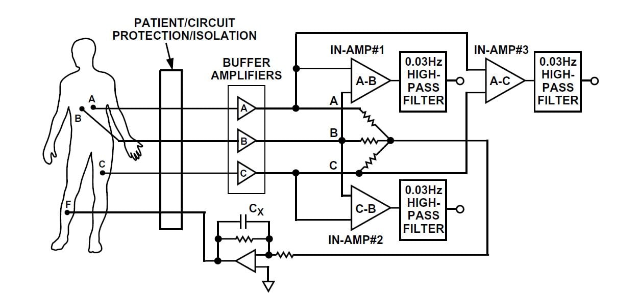
All three instrumentation amps extract the signal differences from sensor electrodes, while the last electrode “F” acts as a ground. Instrumentation amps are used for this device because the biopotential electrodes pick up a huge amount of power line noise, which needs to be rejected so the device can give accurate readings.
Industrial Applications
Instrumentation amps also find usage in industrial automation, where many systems use current flow to relay measurements and control remote installations. In the early twentieth century, industrial complexes would use air pressure to control remote machines, using 3-15psi as the full range, where 3psi represents 0%, system on and 15psi for 100%. Anything less than 3psi meant the system was off or unstable, and would trigger an alarm. Now the industry standard is to use DC current flow analogous to the air pressure, with the range now 4mA-20mA. Incidentally, if you ever wondered what that button on many of our multimeters was that read “4-20mA”, now you know. In this application, current is measured so that two remotely connected devices can communicate, even if they have different grounds. For this to work, the output amplifier for the transmission line must operate very linearly with respect to the input signal and reject any interference caused by mismatched grounds; a perfect candidate for an instrumentation amplifier. Below is a simplified schematic of an integrated instrumentation amp being used in this application, a circuit known as a current transmitter.
.png)
In this figure, U1 represents a lossy transmission line, and R2 is the device on the receiving end that converts the current into some command or measurement value.
In addition to this industrial application, large motor controllers also incorporate instrumentation amps. Typically used to measure current in an H-bridge, the floating inputs of an instrumentation amp make the perfect platform for motor drivers, as motors are usually not referenced to ground.
Conclusion
Instrumentation amplifiers have uses in nearly every field of electronics; they fulfill a specific role in circuits needing the advantages of high input impedance with good gain while providing common mode noise rejection and fully differential inputs. With such widespread use, this is a device every engineer should have in his tool belt.
Related Content


Very Good article
Thank you for the article. Can you please provide a link to your references? I’m especially interested in the Analog Devices application manual? Thank you