Facebook
 Google
 GitHub
 Linkedin
Instrumentation Amplifier Gain Calculator
The instrumentation amplifier calculator will assist in the design and analysis of a conventional instrumentation amplifier circuit by calculating the required resistor values and gain.
Input any 4 of the 5 circuit design variables
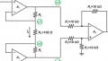
This calculator may be applied to either designing or understanding the behavior of the three op amp instrumentation amplifier design shown in the figure below. This differential amplifier circuit provides a high input impedance, an easily adjustable gain, and a high common-mode rejection ratio. This calculator will determine either the gain or the required resistance values for the instrumentation amplifier.
.jpg)
Instrumentation amplifier circuit schematic
Instrumentation Amplifier Gain Formula:
To determine the output voltage of an instrumentation amplifier in the architecture shown above, we use the following equation:
$$V_o = (V_2 - V_1)(1 + \frac{2R_2}{R_{gain}})(\frac{R_4}{R_3})$$
The instrumentation amplifier gain equation can then be expressed as the following:
$$A_v = \frac{V_o}{V_2 - V_1} = (1 + \frac{2R_2}{R_{gain}})(\frac{R_4}{R_3})$$
If this is a balanced circuit design in which all resistor values except for Rgain are equal to R, we can simplify the output voltage and gain equations to the following:
$$V_o = (V_2 - V_1)(1 + \frac{2R_2}{R_{gain}})$$
$$A_v = (1 + \frac{2R_2}{R_{gain}})$$
Instrumentation Amplifier Applications
The instrumentation amplifier is a type of differential amplifier in which the inputs are buffered by the two additional op amps to provide high input impedance. This high input impedance makes them ideal for analog amplification of signals from sensors, transducers, or a Wheatstone bride.
Further Reading
Related Content