 Facebook
 Google
 GitHub
 Linkedin
Introduction to Power Management: Voltage Regulator ICs
A fundamental challenge that confronts electrical engineers is that of efficiently converting the supply voltage that we have into the supply voltage that we need. The source of electrical energy for an electronic device could be a steady 3 V supply generated by a battery, a noisy 28 V aircraft power bus, 12 V produced by a “wall wart” AC-to-DC power module, or a highly variable voltage produced by a solar panel.
These power sources, though certainly diverse in terms of application environment and performance characteristics, have at least one thing in common: they usually don’t provide the exact type of supply voltage that an engineer needs for his or her circuit. The essence of power-supply design is converting the supply voltage provided by the system into a supply voltage that will allow a circuit to consistently meet its functional requirements. This is accomplished by means of voltage regulation, and though it is possible to create voltage-regulator circuits using discrete components, nowadays it is much more common to use power-management integrated circuits (PMICs).
Linear vs. Switching
Voltage-regulator ICs can be divided into two broad categories based on how an output transistor is controlled. If the transistor’s conductivity is varied in a continuous way, the regulator is described as linear. If the transistor is repeatedly switched between zero conduction and full conduction, we have a switching or switch-mode regulator.
Linear Regulators
Linear regulators have an error amplifier that compares the regulator’s output voltage to an internal reference voltage. As you can see in the diagram below, the error amplifier drives an output transistor that is connected between the input node and the output node. This negative-feedback configuration allows the voltage regulator to maintain a constant output voltage despite changes in input voltage and load current.

The two resistors in this diagram form a voltage divider that determines the mathematical relationship between the reference voltage and the output voltage.
The transistor in a linear regulator is functioning like a variable resistor. The power dissipation of a resistive element is equal to voltage drop multiplied by current; thus, if there is a large difference between the input voltage and the output voltage, a linear regulator will waste a lot of power relative to the required load current. In other words, linear regulators can be very inefficient—energy that could be used to power the circuit is being dissipated as heat simply because we need to convert a high supply voltage into a lower supply voltage.
Linear regulator ICs are popular because they are small and very easy to use, and in sensitive analog applications it may be important to avoid the noise generated by switch-mode regulation. However, when efficiency is a major concern, designers will typically use a switching regulator.
Switching Regulators
Switch-mode regulation is more efficient than linear regulation because the output transistor acts like a switch that is either open (that is, blocking current) or closed (that is, passing current with very little resistance). When current is flowing through the transistor, its resistance is low, and therefore power dissipation is also low.
Switching regulators—which are also called DC/DC converters when they accept a DC input and produce a DC output—come in a variety of circuit topologies, and switching-regulator ICs can be very complex.

This is a basic buck converter topology.
High-current digital ICs are frequently powered by switch-mode regulators; digital circuitry is not negatively affected by switching noise, and the improved efficiency extends battery life and reduces heat generation. In some cases, though, the noise produced by the regulator’s switching action can be problematic, and designers must take measures to reduce the noise amplitude or to suppress electromagnetic emissions that might interfere with other circuits or devices. The following oscilloscope screen capture gives you an idea of what switching noise looks like.

Other Types of Power ICs
Linear and switch-mode voltage regulators are not the only components that provide power-related functionality. The PMIC category also includes specialized battery chargers; gate drivers, which produce high-current signals for controlling transistors; LED drivers, which are optimized for delivering current required by a light-emitting diode; and supervisor circuits, which monitor a supply voltage and produce a reset or notification signal if the voltage falls below a threshold.
Conclusion
This chapter introduced the concept of integrated circuits, explained the difference between analog electronics and digital electronics, and introduced various types of analog, digital, and power-management ICs. The next chapter provides an extensive introduction to a particularly interesting and useful integrated circuit—the operational amplifier.
Related Content


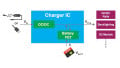


Hey electronics geeks, The voltage regulator mostly preferred to use with voltage supervisor IC, without the voltage regulator IC may get destroyed if the fault condition isn’t resolved within a specified time. In the case of over/under voltage the voltage supervisor IC will help to turn OFF or control enable pin of the regulator IC switch if off.
I have drawn a few schematics as reference for voltage supervisors IC with a voltage regulator IC. You can follow the below reference schematic links, and let me hear any question you have in your mind.
https://www.flux.ai/ramprakashvishnoi8/voltage-regulator-with-supervisor-reset
https://www.flux.ai/ramprakashvishnoi8/tps3839-with-a-boost-converter-tps6126x
Cheers,
Ram