 Facebook
 Google
 GitHub
 Linkedin
Active Rectifier Circuits: Convert Alternating Current to Direct Current
Even signals that would be completely blocked by a typical silicon diode, because they never exceed the diode’s threshold voltage, can be precisely rectified by an active rectifier.
The term “rectifier” comes from a Latin word meaning “straight,” and that’s why we use it to identify a circuit that “straightens out” alternating current—that is, it ensures that current flows only in one direction, even when the source voltage would normally produce current that flows in both the positive and the negative direction.
The most basic rectification circuit is simply a diode, and in fact the word “rectifier” can refer not only to an entire circuit but also to a diode as an individual component. Diodes are simple and effective rectifiers, and they are widely used for this purpose.
However, in some applications the diode’s voltage drop can be problematic. A diode does not begin to conduct significant amounts of current until the voltage across its terminals has reached a threshold, and this means that the diode cannot reproduce the entire positive portion of the input signal.
Also, this diode voltage remains after the device is fully conductive, resulting in power dissipation equal to the voltage across the diode multiplied by the current flowing through the diode.
Op-Amp Rectification
An active rectifier can be implemented as shown in the diagram below.
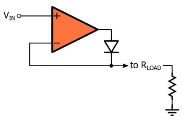
The two essential components are an operational amplifier and a diode. However, it’s important to include a resistor in the circuit diagram because the diode operates by blocking or conducting current, and we need to include load resistance so that this current will be converted into a voltage that we can measure and compare to the input signal.
Understanding the Active Rectifier
The purpose of an active rectifier is to overcome the nonideal rectification behavior of an individual diode. The circuit accomplishes this by using negative feedback and amplification to “bypass” the voltage range in which the diode does not conduct current.
When the diode is conducting, the circuit is essentially a voltage follower: the voltage applied to the load is also the voltage that is fed back to the inverting input terminal, and consequently the op-amp will adjust its output voltage in whatever way is necessary to make the load voltage equal to the input voltage (\(V_{IN}\)).
The following diagram visually conveys this concept, and it emphasizes the role of the virtual short. If the diode is conducting, negative feedback is present.
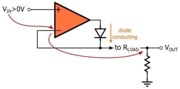
If negative feedback is present, the voltage at the inverting terminal is equal to the voltage at the noninverting terminal, and since the inverting terminal is connected to \(V_{OUT}\), \(V_{OUT}\) equals \(V_{IN}\).
The key to understanding the operation of the active rectifier is to recognize that the circuit functions as a voltage follower even when the input voltage is much lower than the diode’s threshold voltage. If the input voltage is below 0 V, the diode is an open circuit and the inverting input terminal is connected to ground through the load resistor.
As soon as the input voltage goes above ground, there is a positive differential voltage between the two input terminals, and the op-amp’s high open-loop gain results in a large output voltage. This output voltage causes the diode to start conducting current, and the circuit becomes a voltage follower.
The Improved Active Rectifier
The basic active rectifier shown above has limited usefulness in real-life circuits because it relies upon output saturation.
When the input voltage is below 0 V, the diode is an open circuit and there is a negative differential voltage between the op-amp’s input terminals. This negative differential voltage is multiplied by the op-amp’s high open-loop gain, and consequently the output is driven all the way to the negative supply rail.
Forcing an operational amplifier to repeatedly recover from output saturation is in general undesirable, and potentially large swings in output voltage will reduce the circuit’s ability to rectify high-frequency signals.
By modifying the active rectifier as shown in the diagram below, we can prevent output saturation.
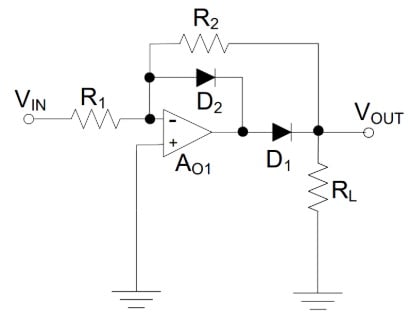
Notice that we now connect the input signal to the op-amp’s inverting input terminal.
When the input signal is above 0 V, \(D_1\) is an open circuit and \(D_2\) conducts. Thus, a negative feedback path is established (which prevents saturation) and the virtual short is active, but the output node is disconnected from the op-amp’s output terminal. Thus, for positive input voltages, the output node is grounded through both \(R_2\) and \(R_L\).
For negative input voltages, \(D_2\) is an open circuit and \(D_1\) conducts. Under these circumstances, the circuit functions as an inverting amplifier, i.e., \(V_{OUT}\) is equal to \(V_{IN}\) multiplied by \(-R_2/R_1\). Thus, this improved active rectifier is actually an inverting rectifier.
Summary
- A rectifier can convert alternating current to direct current. A diode functions as a rectifier because it allows current to flow in only one direction.
- The basic active rectifier consists of an operational amplifier and a diode. It uses negative feedback and high gain to “bypass” the diode’s threshold voltage.
- In the improved active rectifier, an additional diode is used to prevent problems associated with output saturation.


Can someone explain this?
“This diode voltage remains after the device is fully conductive”
- Thx