 Facebook
 Google
 GitHub
 Linkedin
Common Operational Amplifier (Op-Amp) Applications
The term “operational amplifier” refers to a diverse category of integrated circuits that are used very frequently in analog and mixed-signal applications. The operational amplifier is undoubtedly one of the most useful and versatile components available to the electrical engineer.
These devices are relatively easy to understand and implement, and they can be incorporated into circuits ranging from the most basic analog buffer to high-order filters and complex signal generators.
Voltage Follower
As the name implies, the voltage follower is a circuit in which the output voltage follows the input voltage. In other words, \(V_{OUT} = V_{IN}\). As shown in the diagram below, an operational amplifier is the only required component.
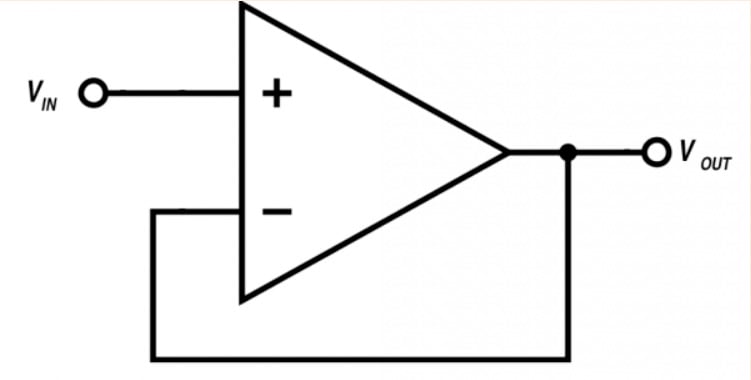
The voltage follower is a good reminder that the value of operational amplifiers goes far beyond amplification. In fact, we frequently design op-amp circuits that are not intended to increase the amplitude of an input signal. In the case of the voltage follower, the desired functionality is buffering.
An op-amp makes an excellent buffer because it provides very high input impedance and very low output impedance. This is exactly what we want when the objective is to efficiently transfer a voltage signal: the high input impedance makes the voltage follower compatible with a wide variety of source circuits, and the low output impedance makes it compatible with a wide variety of load circuits.
The following list summarizes the characteristics of the op-amp voltage follower:
- Unity gain (i.e., \(V_{OUT}/V_{IN} = 1\))
- High input impedance
- Low output impedance
- No phase inversion
Inverting Amplifier
An operational amplifier, when considered as a standalone component, is a differential amplifier with an extremely high gain. However, we typically do not use op-amps as high-gain amplifiers. Instead, we use a negative-feedback configuration to convert the operational amplifier into a low-gain amplifier circuit in which the input-to-output relationship depends on external passive components.
The configuration shown below, called an inverting amplifier, is one of the most fundamental op-amp-based amplification circuits.
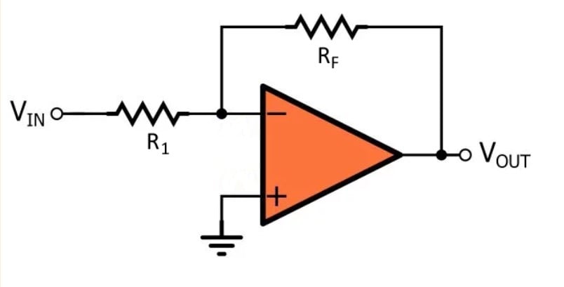
The negative-feedback action causes the gain of this circuit to be almost completely independent of the gain of the op-amp itself. Furthermore, we can precisely control the gain simply by choosing the values of the two resistors. The inverting amplifier also inverts the input signal—that is, it creates 180° of phase shift between the input and the output.
The behavior of the inverting amplifier is summarized as follows:
- Inverts and amplifies the input signal
- Gain = \(–R_F/R_1\)
- Low output impedance
- Input impedance is equal to \(R_1\) and therefore is not necessarily high
Active Filter
In many applications, we can adequately attenuate the high-frequency components of a signal with nothing more than a resistor and a capacitor. One way to improve upon the basic RC low-pass filter is to add a buffer, as shown in the diagram below.
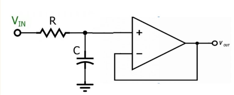
This circuit is really just an RC filter that has been combined with a voltage follower in order to improve the output impedance, but it does bring us one step closer to an active filter—that is, a circuit in which the filtering action relies upon both an amplifying component and passive components.
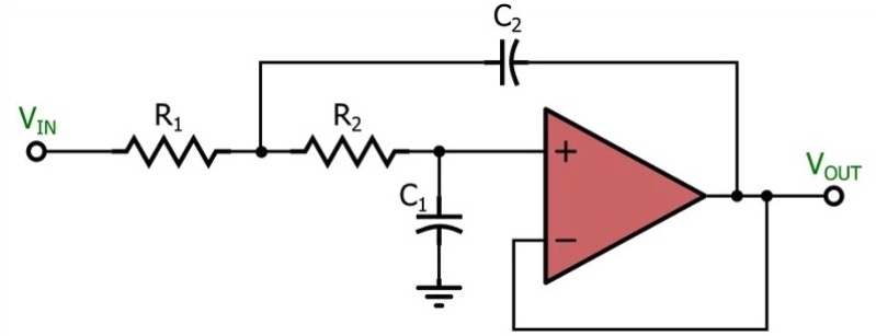
Active filters are important because they provide an effective and convenient means of achieving the improved frequency response of a second-order filter. Engineers often work with signals in which the important frequencies are close to the frequencies that need to be suppressed, and second-order (or higher-order) filters are used to achieve a more rapid transition between the portion of the frequency response that has low attenuation and the portion of the frequency response that has high attenuation.
The diagram below shows an example of an active low-pass filter based on the widely used Sallen–Key topology.
Current-to-Voltage Converter
Operational amplifiers are used as a simple and effective means of converting a current signal into a voltage signal. The most basic implementation, shown in the diagram below, requires only one resistor in addition to the op-amp.
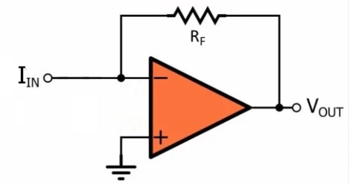
The input current is applied to the inverting input terminal, and the op-amp generates an output voltage whose magnitude is equal to the current multiplied by the feedback resistance (\(R_F \)).
Perhaps the most common application of the current-to-voltage converter, also known as a transimpedance amplifier, is photodiode circuits such as the one shown below.
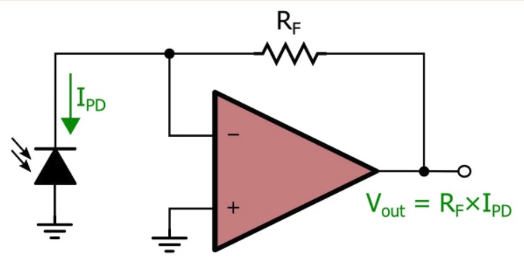
The photodiode generates a current that is proportional to light intensity, and consequently, the overall circuit generates a voltage signal that is proportional to light intensity.
Summary
- Op-amps are extremely versatile and are used in a wide variety of electronic circuits.
- The voltage follower is a simple circuit that requires only an operational amplifier; it functions as an effective buffer because it has high input impedance and low output impedance.
- An inverting amplifier consists of an op-amp and two resistors. The op-amp provides the amplification, but the values of the resistors determine the gain.
- An op-amp can work in conjunction with resistors and capacitors to generate a second-order frequency response; these circuits are called active filters.
- An op-amp combined with one feedback resistor creates a circuit that accepts an input signal from a current source and produces a corresponding output voltage.
Related Content


The current to voltage converter is stupidly drawn. Vout should be the normal -I*Rf
The inverting amplifier is always drawn the way you did, but it’s harder to understand. When it’s drawn as a divider, it’s much easier to understand where gain comes from.