Facebook
 Google
 GitHub
 Linkedin
Choosing the Right Transistor: Understanding Low-Frequency MOSFET Parameters
This article provides an overview of various characteristics and specifications that are relevant to low-frequency MOSFET operation.
This article provides an overview of various characteristics and specifications that are relevant to low-frequency MOSFET operation.
Related Information
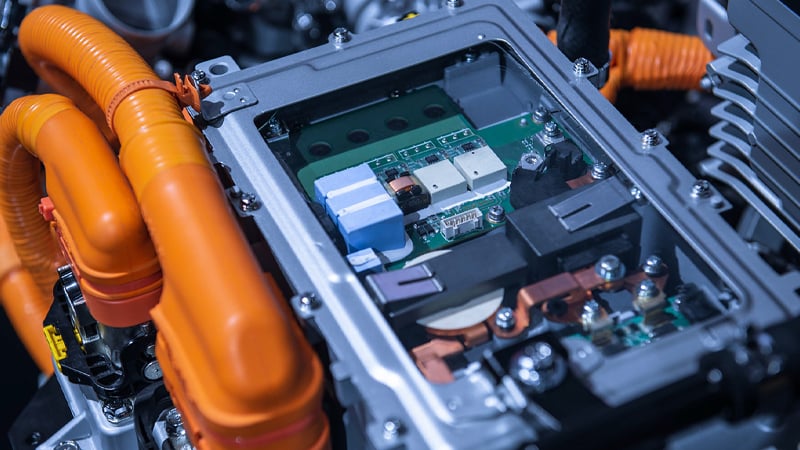
Let’s say you’re designing a motor-control circuit, or a relay driver, or a reverse-polarity protection circuit, or an output buffer for an op-amp. You realize that you want to use a MOSFET, and of course you direct your browser to the site of your favorite distributor. The trouble is, you’re going to find a lot of MOSFETs—if you’re using the larger distributors you’ll see thousands of part numbers. How do you even begin to find the device that is most appropriate for your application?
The first step is to realize that you probably won’t find the most appropriate part. That would take a long time and is not worth the effort; the goal is to achieve adequate functionality and performance, and this can be achieved with an adequate MOSFET. In other words, when you see a part that has acceptable specs and an acceptable price, add it to the BOM and move on to the next design challenge. If you’re designing a Mars rover you’ll need to be a bit more careful with component selection, but my guess is that you’re not designing a Mars rover (because if you are, you probably know more about this topic than I ever will).
But how do we go about finding an adequate MOSFET for a given application? Well, you need to understand the requirements of your system and the various parameters that characterize MOSFET operation, and then you need to combine all that information into a process of gradually narrowing down the list of possible parts (while also considering price and form factor). This article (and a second article on a similar topic) will help you with this process by explaining important electrical parameters of discrete MOSFETs.
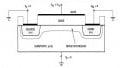
On-State Resistance
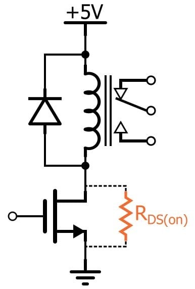
I’m going to be brief here because I’ve already written an entire article dedicated to this one parameter (the link is at the beginning of this article under “Related Information”). More resistance means more power dissipation, so we generally look for devices that have lower on-state resistance. However, if miniaturization is an important design goal, you need to keep in mind that lower on-state resistance corresponds to a larger FET.
Threshold Voltage
A MOSFET will not conduct significant current until VGS—i.e., the voltage applied to the gate relative to the voltage applied to the source—is above a certain value referred to as the threshold voltage. You need to make sure that your FET’s threshold voltage is lower than the output voltage of your drive circuitry.
As is usually the case with physical phenomena, MOSFET conduction is not an “on/off” sort of thing. The FET doesn’t achieve maximum performance as soon as the gate exceeds the threshold voltage by a few millivolts:

Courtesy of Vishay Siliconix. Plot taken from this datasheet; the FET in question has a maximum threshold voltage of 2.5 V.
If you’re limited to relatively low drive voltages, you can inspect the performance plots and try to determine which parts are more tolerant of low VGS.
The Maximums
It’s good to try to optimize performance by choosing a MOSFET with suitable threshold characteristics and low on-state resistance, but it’s also important to ensure that you don’t destroy or seriously weaken the device, and this is where “the maxes” come into play.
Max Drain-Source Voltage and Gate-Source Voltage
These are the highest voltages that can be safely applied across the drain and source pins and across the gate and source pins. For the drain-source voltage, we’re referring to the off state (in the on state the drain-source voltage will be low because the channel resistance is low). The maximum gate-source spec is given with positive and negative voltages, so the device could be in the on state or the off state.
Remember that these are not the maximum drain voltage and the maximum gate voltage: the source does not have to be grounded, so the drain-source voltage is not always the same as the drain voltage and the gate-source voltage is not always the same as the gate voltage.
Max Drain Current
In the context of low-frequency parameters, this refers to the maximum continuous current that the device can sustain. (The maximum transient current is significantly higher.) This spec is not quite as straightforward as you might think, because it could be based directly on current flow (i.e., the amount of current that the device can physically tolerate) or on the amount of current that would create enough power dissipation to result in unacceptably high junction temperatures. In the latter case, the actual maximum drain current depends on thermal conditions.
Max Total Power Dissipation
This spec is not particularly helpful because power dissipation does not directly damage a device. The real problem is temperature, and the relationship between power dissipation and temperature is highly variable and not easy to accurately predict. Anything that helps to move heat away from the device—thermal vias, copper pours, heatsinks, fans—will allow the device to dissipate more power without overheating.
Temperature Effects
Changes in temperature lead to changes in just about everything else. The following plots give you some examples of how temperature can influence MOSFET electrical parameters.

Variation in threshold voltage vs. temperature. Taken from this Vishay datasheet.

Taken from this Diodes Inc. datasheet.

More current means more power dissipation, and this in turn brings the device closer to its maximum junction temperature. Thus, allowable drain current decreases as ambient temperature increases. Diagram taken from this app note published by NXP/Nexperia.
Conclusion
This article reviewed low-frequency MOSFET characteristics that play an influential role in device selection. In the next article, we’ll look at dynamic parameters, which are especially important nowadays because we so often use FETs as switch-mode controllers (e.g., in switching regulators, LED dimmers, audio amplifiers) instead of linear controllers.