Facebook
 Google
 GitHub
 Linkedin
The Many Definitions of Electrical Balance
In this article, we'll use practical examples to define and demonstrate the concept of electrical balance. In particular, we’ll examine differential signals and coax currents.
The importance of distinguishing between balanced and unbalanced systems has long been understood. Back in 1939, Nils E. Lindenblad described the need for a balun on one of the Empire State Building antennas as follows:
The line balance converter [...] involves the principle that the outer conductor of a coaxial line must be made electrically free from its surroundings in order not to destroy the balance of a system to which it is connected.
In the above case, a coax cable is connected to a dipole antenna. The outer face of the coax shield supports currents entirely unrelated to the internal currents, which are carried on the center conductor and inner face of the shield.
This undesired current path along the outside of the coax doesn't propagate with the typical transverse electromagnetic (TEM) mode like the interior of the coax, with its tightly contained fields. Instead, the entire length of coax turns into another antenna, which will couple into the rest of the system.
To restore order, we then need to constrain the boundary conditions of the coax so that the center conductor and shield carry equal and opposite currents at the ends. In other words, we must enforce a condition of balance.
Radio designers aren't the only ones who must understand the concept of balance. The additional current on the coax shield is a common-mode current. If you are at all familiar with EMC or signal integrity, you will understand the implications of having undesired common-mode currents in a system. Every engineer working with hardware should know how balance and common-mode current relate to each other, and how they impact a system.
But what exactly is balance, and how do we know when it's important? The answer seems to depend on who you ask. The concept of balance is used across any number of domains, leading to many different definitions.
In this article, we'll attempt a reconciliation of sorts, and do so cautiously. We're not going to develop a new theory of balance, we're simply going to clarify what everyone has been talking about all this time.
Developing the Concept of Balance
Figure 1 demonstrates the basic operation of differential signaling between a generator and a load.
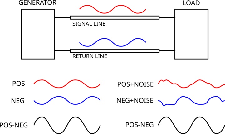
Figure 1. Differential signaling eliminates common-mode noise. Image used courtesy of Sam Gallagher
You're likely familiar with the idea that a system with purely differential signals is immune to interference because noise introduced into one signal is equally introduced into the other. A common example is data transfer over a twisted pair. To help us generalize this concept, let's examine that example further.
The Twisted Pair
In a twisted pair, capacitive coupling of noise onto two conductors is "eliminated" by the fact that the same amount of noise is coupled into both. The differential receiver only cares about the difference between the signals on the two conductors. The two signals being equal and opposite along the length of the transmission line is essential to maintaining the noise-cancelling effects on the receiving end. (The common-mode rejection at the receiver will also have a significant impact, of course.)
In short, the signals need to be balanced with each other, i.e. equal and opposite. They also need to be balanced with respect to any interfering signals and their corresponding sources, i.e. coupled equally to them.
A similar effect occurs with the antennas in the Empire State Building, as described in the Lindenblad article we quoted above. That publication happens to include one of the earliest mentions of a balun. If we're trying to understand balance, why not see how these early engineers understood the problem? It should at least be historically informative.
A Historical Example
There were two antennas designed for the top of the Empire State Building, one for television (the 'vision antenna') and one for audio (the 'sound antenna'). It was necessary that the two antennas not couple into each other.
To meet this requirement, the vision antenna was made from four ellipsoid conductors. The sound antenna was similar to a circular loop antenna, but made of folded dipoles. The design of the sound antenna can be seen in Figure 2. Note that all lines in the figure represent wires.
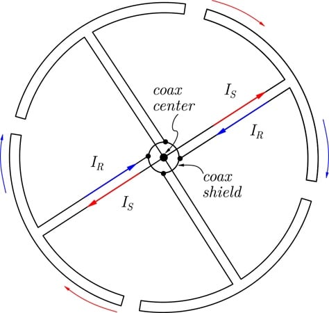
Figure 2. Empire State Building sound antenna, schematic representation. Image adapted from Lindenblad
Here we have four loops like spokes of a wheel. Two diametrically opposed dipoles have signal currents coming from the coax center (shown in red) flowing around the segments of their thin loops, and then returning to the coax shield (shown in blue).
The system is designed so that undesired currents induced by the vision antenna, which was installed vertically several meters below this one, will be in the same direction along a given conductor. The induced currents on a given pair of signal lines will thus be equal and in the same direction, passing over rather than entering into the coax feed line. To quote from the Lindenblad article:
The common feed line is so connected to the feeders of the individual radiators that the currents in opposite radiators become opposite. Currents, which on the other hand are induced by the turnstile antenna, are of same direction in opposite radiators. They must therefore balance each other without entering the common feed line.
For this to work, however, we need current to be conserved on the antennas. Thus, the transmission line feeding the antenna must not allow any additional current path apart from its equal and opposite currents on the center conductor and shield. In other words, the coax must enforce the condition of balance when feeding the antenna. The solution was a "line balance converter," which is now known as a bazooka balun.
That's it for the historical example. Let's look at some other, more contemporary, cases.
Two Final Examples
Consider a twin lead transmission line with one conductor longer than the other. Let's assume the noise is induced on both conductors equally. The common-mode induced currents typically cancel out. However, because they are traveling different distances, in this case they will be phase shifted at the receiving end.
As a result, these currents will only partially cancel out. Although the coupling between the two conductors and the nearby ground conductor is nearly equal, we can still see that the system should not be considered balanced.
As a final example, imagine a coax cable in free space feeding a twin lead cable through an impedance-matching network, with both cables terminated in their respective characteristic impedance.
Let's say the system operates at 433 MHz. There is no explicit ground plane in the system. Likewise, there are no reflections due to mismatch, and no antennas connected anywhere.
Surely this system is not in jeopardy of being unbalanced. But alas, the system shows both high sensitivity to noise pickup and high radiated emissions. Even standing near the coax cable causes changes in the signal strength and system behavior! Repeating this experiment with two coax cables, we find no problems. So what's the issue?
With some investigation, we will find that there is mode conversion at the junction between the twin lead and the coax, and that this is a general property of connecting a transmission line with symmetric signal and return lines (the twin lead) to a transmission line with asymmetric signal and return lines (the coax).
Defining Balance
There are many ways to define the balance of an electrical system. It's difficult to find a suitably general definition that will cover all the examples above, but many have tried. Here are a few samples of what's out there:
- Henry Ott defines a balanced circuit as a "two-conductor circuit in which both signal conductors, and all circuits connected to them, have the same non-zero impedance with respect to a reference (usually ground) and all other conductors" (Electromagnetic Compatibility Engineering, p. 158).
- In his book Antenna Engineering, W. L. Weeks writes that "a balanced system is one in which the two conductors are respectively above and below ground potential by the same amount."
- In the same book, Weeks also admits another definition for antennas and transmission lines: "two halves of a symmetric transmission-line or antenna system are said to be balanced if they carry the same (but opposite) current, or unbalanced if their currents are unequal."
We thus have three definitions of balance, neatly corresponding to impedance, potential, and current. For the purposes of this article, I'm going to simplify these into just two. The first is what I will refer to as the coupling definition of balance, based on the impedance or potential between a system of conductors and a reference conductor. The second definition is the point definition of balance, based on the magnitudes of the currents at a given position along a two-conductor distributed system.
Understanding the Coupling and Point Definitions
A little thought will convince you that both definitions must refer to a system of two primary conductors in a transmission line (including differential pairs). The coupling definition requires a third conductor in order to complete the definition, while the point definition only requires a pair of conductors.
The coupling definition is easier to understand intuitively because electrical engineers have a well-developed set of tools for dealing with capacitive coupling between conductors. (Never mind the business of inductive coupling for now.) However, the point definition is in terms of currents, which are relatively easy to measure. This definition also generalizes better to greater numbers of conductors, as well as to antenna problems.
Furthermore, the point definition makes it clear that the balance of a system is not only a function of how it's positioned relative to other conductors. It is also a function of how the system is connected to a generator and load, and how it is driven.
Modeling Electrical Balance
To make our discussion more concrete, let's examine the two system models in Figure 3.
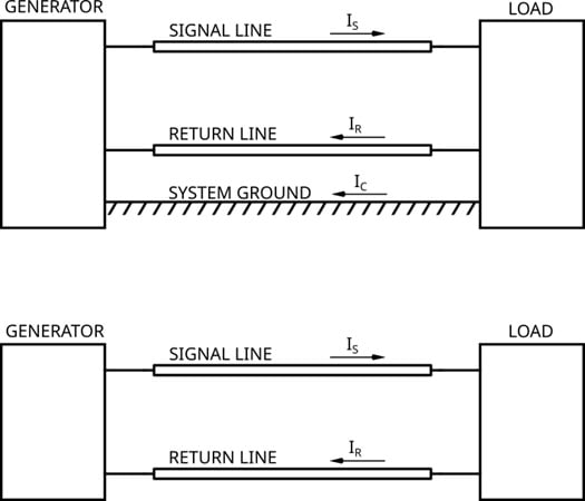
Figure 3. Two models for defining electrical balance. When coupling occurs between either line and the system ground, that coupling can be included in the generator or load blocks. Image used courtesy of Sam Gallagher
The first model includes a system ground. The second has no system ground. Both are driven by a "generator" block, and transfer signals into a "load" block. These simple models are general enough to describe many cases of interest in data transmission and transmission line/antenna problems.
We assume the signal and return lines have currents which are position-dependent. This means that you can have standing waves and other wave features in the currents along their lengths. Coupling between the signal and return line and the system ground can be included in the generator and load blocks, as can any additional connections to transmission lines or antennas.
With these models in mind, we can restate our two variant definitions:
- Coupling definition of balance: A two-conductor transmission line is balanced when its signal and return lines are equally coupled to either system ground or a third conductor.
- Point definition of balance: A two-conductor transmission line is balanced at a position when the current on the signal line is equal and opposite to the current on the return line at that same position.
Wrapping Up
In this article, we explored different ways of defining electrical balance, ultimately coming up with two simple definitions of our own. We used practical examples as test cases to refine the concepts and guide our discussion, as well as simple models to provide context. In the next article, we'll dive deeper into this topic by exploring the close relationship between electrical balance and common/differential modal analysis.
Featured image background used courtesy of Adobe Stock