 Facebook
 Google
 GitHub
 Linkedin
Boolean Algebra Basics—An Overview of Boolean Logic
New to digital logic, want a refresher, or to dive deeper into Boolean algebra? This article teaches the basics of Boolean algebra and prepares you for further learning.
For those with little or no exposure to digital logic and those wanting a refresher or to understand Boolean algebra at a deeper level, this article walks through the basics of Boolean algebra. The goal is to prepare you for subsequent articles that delve deeper into aspects of Boolean algebra.
Boolean Logic or Digital Logic—What is Boolean Algebra?
Our focus is more geared toward engineers and technicians and not toward mathematicians and philosophers; thus, we describe Boolean algebra as the manipulation of two-state signals to implement logic functions. At its core is a deceptively simple set of concepts, namely signals, that can take on only one of two values (states) at any moment, combined with three fundamental operations that the user can apply to those signals.
For most engineers and technicians, the terms "digital logic" and "Boolean logic" are synonymous. In contrast, "Boolean algebra" is slightly different, implying a more math-oriented approach to analyzing or designing digital systems.
Boolean algebra (named in honor of George Boole) involves only two values—FALSE and TRUE. Sometimes we use different names depending on what makes sense; common names are {F, T}, {LO, HI}, {L, H}, or {0, 1}.
Like normal algebra, we have Boolean operators that take one or two operands and produce a value (a Boolean value). An "operand" is nothing more than a value (or signal), and an "operator" is nothing more than some manipulation of the values to produce a result. In normal arithmetic, the expression "2 + 3" has two operands (the "2" and the "3") and one operator (the "+"), which produce the result "5".
Boolean algebra involves three primitive operators, one unary (takes one operand) and two binary (takes two operands)—the unary operator is the logical negation (NOT) operator. On the other hand, the binary operators are the logical disjunction (OR) and logical conjunction (AND). That's all there is to keep track of: two possible values, FALSE and TRUE, manipulated by three operators, NOT, OR, and AND.
Now is a good time to point out that different terminology is used in different fields. We speak about logic operators and logic functions in more math-centric fields, while in more engineering-centric fields, we talk about logic gates. However, in each case, we are taking one or more input signals (operands) and using a logic gate (logic operator) to produce an output signal (result) that depends only on the current input signals.
As a quick note, for those who already know about combinational logic and sequential logic, we will keep the discussion focused on combinatorial logic—for those who don't know about these two types of logic, you can ignore this note.
Since AAC is very engineering-centered, we will use the terminology most commonly found in engineering fields. However, as we introduce the basic gates in the next section, we will present the operator notation used in engineering and math. This approach can be useful because most engineers and technicians will have discussions from time to time with people that use non-engineering notation.
Boolean Truth Table
Since Boolean algebra is so constrained as to the values the signals can take, we can describe or even define functions by exhaustively listing all possible combinations of the input signals along with the value of the resulting output. This list is known as a truth table.
An example truth table can be seen in Table 1.
Table 1. An example truth table.
| A | B | Y |
| F | F | T |
| F | T | F |
| T | F | F |
| T | T | T |
In this table, 'A' and 'B' are the input signals, and 'Y' is the output signal. The usual convention is that inputs are listed in the left-hand columns and outputs in the right-hand columns. If there are any, intermediate signals go between the input and output columns. Since we will only discuss gates with a single output and no intermediate signals, the right-most column is the output, and all other columns are inputs.
This example table is sufficient to define a particular Boolean gate. If we were to describe this gate in words, we might say something like, "The output is TRUE if and only if both inputs are the same." We might then give this gate the name "Equality Gate" with the symbol "EQ" and write expressions as:
$$Y = A \text{ EQ } B$$
From there we can say that Y is TRUE if and only if A equals B.
Concerning simple gates (and even moderately complex logic functions), truth tables are the preferred way of describing and defining them because they are unambiguous.
For instance, what if we just said that we wanted a gate whose output was TRUE if the two inputs were equal? This situation is ambiguous because we haven't actually said what the output should be when they aren't equal. Similarly, if we say that we want a gate whose output is TRUE only when the outputs are equal, we haven't actually said what the output should be when they ARE equal. We've only ruled out what they can be equal to when they aren't equal.
We could certainly argue that in both of these cases, "it's obvious"—and, in these simple cases, it would be a very strong argument. However, in general, it may not be obvious, and we end up relying on the person reading the description to interpret it the way we did when we wrote it. This situation can be a recipe for miscommunication and potential disaster.
A truth table leaves little to no room for misinterpretation (provided that we use a "proper" truth table, meaning that all possible input combinations are included).
Condensed Truth Tables
Table 1 above has exactly one row for each possible combination of inputs and is therefore known as an "explicit" or a "fully-enumerated" truth table. But the number of rows needed for such a table grows exponentially with the number of inputs.
For instance, a device with just six inputs would require sixty-four rows. Not only would this take up a lot of space, but it makes the truth table much more difficult to comprehend for most humans. So we devise shortcuts to enable us to describe multiple rows from the explicit table in a single row of what is known as a "condensed" truth table. Several conventions are used, but here we will only use one: the "don't care."
Consider the following table in Table 2.
Table 2. An example condensed truth table.
| A | B | Y |
| 0 | X | 0 |
| X | 0 | 0 |
| 1 | 1 | 1 |
The 'X' in a given cell means that that row applies for ANY value of that input. So the first row of the above table says that if A is 0, the output is 0 regardless of what value B might have. Similarly, it says that if B is 0, the output is 0, regardless of what value A might have.
One potential problem with a condensed truth table is when multiple rows apply to the same set of input values. For instance, which row governs the behavior when both A and B are 0?
Since both the first and second rows apply, the table is "over-defined." However, as long as all rows that apply to a given set of inputs produce the same output, the table is consistent and still valid. If they are inconsistent, then the table is not an accurate truth table.
Note that a fully-enumerated truth table can never be invalid—it might be "wrong," meaning that it doesn't represent the logic function we wanted. Still, it will always represent a valid Boolean function.
The Three Fundamental Boolean Operators
Each of the three fundamental Boolean operators, NOT, OR, and AND, has a schematic symbol used for them (there's more than one, but the ones we show here are by far the most common) and a truth table that defines them.
This section will provide these plus the more common notations used to express them in engineering, programming, and math/logic contexts. Keep in mind that the syntax used by a particular programming language is specified by that language and may be completely different than what is shown here, which is the dominant notation in the C-based languages. Also, programming languages deal with variables that can take on more than just two values, so many have multiple operators that deal with this situation in different ways.
As this is well beyond the scope of this treatment, we will not distinguish between these various methods. So, remember that while the programming operators given represent the same logical operation, they are NOT equivalent in the details of how that operation is applied.
The NOT Gate (Logical Negation)
To get started, Figure 1 shows the symbol for a NOT gate.
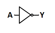
Figure 1. The symbol for the NOT gate
Next, in Table 3, you'll see a truth table for the NOT gate.
Table 3. NOT gate truth table.
| A | Y |
| F | T |
| T | F |
|
Engineering |
$$ Y \; = \; \overline{A} \; = \; A' \; = \; NOT(A) \; = \; NOT \; A \; = \; -A $$ |
|
Programming |
$$ Y \; = \; !A \; = \; \tilde{} A $$ |
|
Math and Formal Logic |
$$ Y \; = \; \lnot A $$ |
Also known as logical negation, this unary operator merely produces the opposite value of the operand. In common English, we might say, "Y is true if A is NOT true."
Notice that, particularly in engineering contexts, we can specify logical negation in multiple ways. In engineering, the three most common ways are with:
- An overbar
- An apostrophe after the operand (known as a "postfix operator")
- A function-like syntax
With the function-like syntax, the name might be NOT(), INV(), or NEG() for "not," "inverse," or "negation," respectively. You may also see a negative sign used before the operand (known as a "prefix operator"); however, this is becoming increasingly uncommon.
Additionally, the overbar is easy to write manually, but it is difficult to type into a text document or a computer program; thus, the postfix apostrophe is widely used.
The OR Gate (Logical Disjunction)
Next, we'll take a look at the OR gate. Figure 2 shows the symbol for an OR gate.
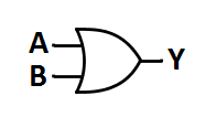
Figure 2. OR gate symbol.
Table 5 below shows the truth table for the OR gate.
Table 5. OR gate truth table.
| A | B | Y |
| F | F | F |
| F | T | T |
| T | F | T |
| T | T | T |
|
Engineering |
$$ Y \; = \; A + B \; = \; OR(A,B) \; = \; A \; OR \; B $$ |
|
Programming |
$$ Y \; = \; A \; | \; B \; = \; A \; || \; B $$ |
|
Math and Formal Logic |
$$ Y \; = \; A \lor B $$ |
Also known as logical disjunction, this binary operator produces a TRUE output if either of its operands is TRUE. Put another way; it produces a FALSE output if and only if both of its operands are FALSE. In common English, we might say, "Y is true if A is true OR B is true."
When we speak of signals that are OR-ed together, we often talk about the result being the "sum" of those signals. This usage stems from using the '+' symbol for the OR operator. This terminology is widely and formally accepted. However, it is generally considered poor form to say that we are "adding" these signals together, though you will hear it from time to time.
The AND Gate (Logical Conjunction)
The final gate we will look at in this article is the AND gate. Figure 3 shows the symbol for the AND gate.
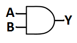
Figure 3. The symbol for the AND gate.
Next, Table 7 will show the truth table for an AND gate.
Table 7. AND gate truth table.
| A | B | Y |
| F | F | F |
| F | T | F |
| T | F | F |
| T | T | T |
Lastly, Table 8 goes over some common ways of expressing AND.
|
Engineering |
$$ Y \; = \; A \cdot B \; = \; AB \; = \; (A)(B) \; = \; AND(A,B) \; = \; A \; AND \; B $$ |
|
Programming |
$$ Y \; = \; A \; \& \; B \; = \; A \; \&\& \; B $$ |
|
Math and Formal Logic |
$$ Y \; = \; A \land B $$ |
Also known as logical conjunction, this binary operator produces a TRUE output if and only if BOTH of its operands are TRUE or, put another way, it produces a FALSE output if either of its operands is FALSE. In common English, we might say, "Y is true if A is true AND B is true."
When we speak of signals that are AND-ed together, we often talk about the result being the "product" of those signals. This usage stems from the various notations for multiplication used for the AND operator. This terminology is widely and formally accepted. However, it is generally considered poor form to say that we are "multiplying" these signals together, though you will hear it once in a while.
What About XOR and Others?
Some may wonder why XOR (i.e., exclusive-OR) hasn’t yet been mentioned. The reason is that XOR is not a primitive operator in Boolean algebra but rather a composite operator since it can be defined in terms of the primitives already given. Still, it—and a few other composite operators—are worthy of some attention.
The symbol for XOR is shown in Figure 4, while the defining truth table is presented in Table 9.
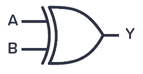
Figure 4. The symbol for the XOR gate.
Table 9. XOR truth table.
| A | B | Y |
| F | F | F |
| F | T | T |
| T | F | T |
| T | T | F |
Some of the common ways of expressing it are shown in Table 10.
|
Engineering |
$$ Y = XOR (A, B) = A \oplus B $$ |
|
Programming |
$$ Y = A^B $$ |
|
Math and Formal Logic |
$$ Y = A \; \underline{v} \; B = A \oplus B $$ |
It is readily verified that the XOR truth table is produced by the following equation given in terms of the primitive operations, thus establishing it as a composite operator.
$$ Y = A \oplus B = \overline{A} B \; + \; A \overline{B}$$
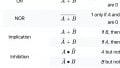
There are three other common composite operators: XNOR, NAND, and NOR, whose symbols and truth tables are shown in Figure 5.
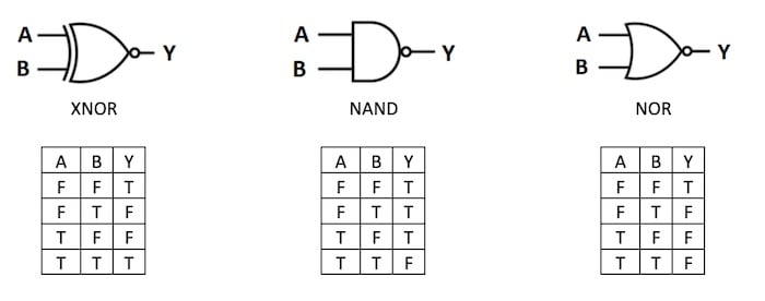
Figure 5. Additional common composite operators.
The equations that produce these truth tables, in terms of the primitive operations, are shown in Figure 6.

Figure 6. Primitive expressions for the common composite operators.
XOR is a sufficiently common operation for which the operator symbol has gained wide acceptance and is commonly seen in Boolean equations. This, however, does not make it a primitive operator. The other gates also have operator symbols; however, the one for XNOR is rarely seen while the ones for the other operations are seldom seen outside of formal logic proofs.
For a more in-depth look at the XOR gate, please see our textbook page "The Exclusive-OR Function: The XOR Gate."
For additional universal logic gate information, please see our article on "Universal Logic Gates."
Operator Precedence and Associativity
Operator precedences (also known as the order of operations) are rules that dictate which operator is executed first when we would otherwise have the choice of picking between two different operators (or, more correctly, two operators of different precedence).
Operator associativity, on the other hand, is simply a rule that dictates which operator is executed first when we would otherwise have the choice of picking between two operators that are the same (or, more correctly, two operators of the same precedence).
Since a given Boolean expression, if evaluated according to the precedence and associativity rules, might not implement the desired logic function, we can override those rules using parentheses. Strictly speaking, these parentheses are simply another operator with the highest precedence
Before discussing precedence and associativity rules for Boolean algebra, let's examine them for the normal algebra and arithmetic we are comfortable using. In the absence of parentheses, we know that multiplication and division have precedence over addition and subtraction. This situation is why multiplication and division are said to have "higher precedence" or be "higher order" than addition or subtraction. We also know that if we have multiple multiplication and/or division operators, we execute them left to right; the same goes for multiple addition and/or subtraction operators. This is known as "left associativity."
Let's examine how these rules are applied to the following expression.
$$A + B * C / D - E + F * G / H * I - J * K + L$$
Since multiplication and division are the highest precedence operators present, we first split the expression into groups that contain only these two operators. We'll use square brackets for this purpose (we will remove these later).
$$A + [B * C / D] - E + [F * G / H * I] - [J * K] + L$$
Within each group, "factors" are all operands for a multiplication or division operator. We evaluate these operators according to associativity, which is left-to-right (left associative) for multiplication and division.
$$A + [((B * C) / D)] - E + [(((F * G) / H) * I)] - [(J * K)] + L$$
At this point, we have "terms" that are all operands for an addition or subtraction operator. We could have removed the square brackets at this point, but they are useful in visually identifying terms made up of multiple factors. From here, we can now evaluate the addition and subtraction operators according to their associativity (i.e., left associative in this case). Let's go ahead and remove the square brackets at this time.
$$(((((A + ((B * C) / D)) - E) + (((F * G) / H) * I)) - (J * K)) + L)$$
This equation is known as a "fully-parenthesized" expression whose significance is that it is independent of the precedence and associativity rules. The reason is simple, those rules dictate which operator to evaluate when we have a choice, but a fully-parenthesized expression gives us no such choices.
Shifting our attention to Boolean algebra, we discover that there are no precedence and associativity rules that are universal. This aspect is particularly true when we start adding more operators, which are nothing but shortcut notations for certain combinations of the three fundamental ones.
Programming languages, by their nature, have well-defined precedence and associativity rules; however, they may vary significantly from one language to another. For this reason, it is best to write Boolean expressions with a liberal dose of parentheses.
With that in mind, most programming languages have converged on a fairly consistent convention, which is a reasonably natural, albeit somewhat arbitrary, outgrowth of the operator notation used. In normal arithmetic, the unary minus sign (the negative sign) has higher precedence than either multiplication or addition.
Since we use the multiplication symbol for AND and the addition symbol for OR, this leads to the Boolean precedence of NOT, AND, and OR (in order from highest to lowest). As is the case with most binary operators, AND and OR are both left associative. The associativity of NOT depends on the notation used. If a prefix operator is used, such as the '~', the '!', the '$$\lnot$$', or even the non-function-like 'NOT', then the operator is right associative. On the other hand, if a postfix operator is used, such as the trailing apostrophe, the operator is left associative.
Left Associative NOT:
$$\text{NOT NOT} A = \text{NOT (NOT} A)$$
$$\sim \sim A = \sim (\sim A)$$
If these were left associative, we would have NOT NOT A being the same as (NOT NOT) A, which is nonsensical since an operator operating on an operator is undefined (though, yes, we could define it if we wanted to).
Right Associative NOT:
$$A' ' = (A')'$$
Similar to the prefix operator, if this postfix operator wasn't left associative we would have A' ' = A (' ') which would be undefined.
So let's consider the following example by fully parenthesizing it.
$$Y = A \text{ AND NOT } B \text{ OR NOT } A \text{ AND } B = A B' + A' B $$
We start with the highest precedence operator, the NOT, and get:
$$Y = A \text{ AND } (\text{ NOT } B) \text{ OR (NOT } A) \text{ AND } B = A (B') + (A') B$$
We then move to the next highest, the AND, and get:
$$Y = (A \text{ AND (NOT } B)) \text{OR ((NOT } A) \text{ AND } B) = (A (B')) + ((A') B)$$
And finally, we only have one remaining operator, which we will parenthesize just for completeness to get:
$$Y = ((A \text{ AND (NOT } B)) \text{ OR ((NOT } A) \text{ AND } B)) = ((A B')) + ((A') B))$$
One of the common mistakes that people make is failing to recognize that, using these very common rules of precedence, that
$$ AB' \; \neq \; (AB)' $$
Though this WOULD be true if all three operators were deemed to be of the same precedence and to be left associative, which would be unusual but not unheard of.
Instead:
$$ AB' \; = \; (A)(B') $$
Diving Deeper Into Boolean Algebra
This has been a pretty lightweight article that has hopefully prepared you for a number of articles that will explore many aspects of digital logic and Boolean Algebra at a much deeper level -- in fact at a level deeper than most courses go. This is useful because to truly master digital logic design, and it is necessary to be fully conversant with the concepts and subtleties upon which it is based and to also be aware of the common misconceptions and fallacies that frequently trap less well-prepared designers.
Interested in learning more about Boolean algebra? Read on in the next article in the series: Boolean Identities


Regarding the expression A+B∗C/D−E+F∗G/H∗I−J∗K+L above, I have never seen subtraction or division in boolean algebra. What logical operations do they represent?
XOR gets no love in the article? Pretty big miss, IMHO. It is a primitive operator, along with NOT, AND and OR.