 Facebook
 Google
 GitHub
 Linkedin
The Karnaugh Map Boolean Algebraic Simplification Technique
Learn about the Karnaugh map (K-map) technique for Boolean algebraic simplification. What advantages and disadvantages do they have?
This article provides insight into the Karnaugh map (K-map) Boolean algebraic simplification technique via a few examples. It also includes a brief note on the advantages and disadvantages of K-maps.
Introduction
Digital electronics deals with discrete-valued digital signals. In general, any electronic system based on digital logic uses binary notation (zeros and ones) to represent the states of the variables involved in it. Thus, Boolean algebraic simplification is an integral part of the design and analysis of a digital electronic system.
Although Boolean algebraic laws and DeMorgan's theorems can be used to achieve the objective, the process becomes tedious and error-prone as the number of variables involved increases. This necessitates using a suitable, relatively-simple simplification technique like that of the K-map, introduced by Maurice Karnaugh in 1953.
A Typical K-Map
The K-map method of solving the logical expressions is referred to as the graphical technique of simplifying Boolean expressions. K-maps are also referred to as 2D truth tables as each K-map is nothing but a different format of representing the values present in a one-dimensional truth table.
K-maps basically deals with the technique of inserting the values of the output variable in cells within a rectangle or square grid according to a definite pattern. The number of cells in the K-map is determined by the number of input variables and is mathematically expressed as two raised to the power of the number of input variables, i.e., 2n, where the number of input variables is n.
Thus, to simplify a logical expression with two inputs, we require a K-map with 4 (= 22) cells. A four-input logical expression would lead to a 16 (= 24) celled-K-map, and so on.
Gray Coding
Further, each cell within a K-map has a definite place value obtained using an encoding technique known as Gray code.
The specialty of this code is the fact that the adjacent code values differ only by a single bit. That is, if the given code-word is 01, then the previous and the next code-words can be 11 or 00, in any order, but cannot be 10 in any case.
In K-maps, the rows and the columns of the table use Gray code-labeling which in turn represents the values of the corresponding input variables. This means that each K-map cell can be addressed using a unique Gray Code-Word.
These concepts are further emphasized by a typical 16-celled K-map shown in Figure 1, which can be used to simplify a logical expression comprising of 4-variables (A, B, C, and D mentioned in its top-left corner).
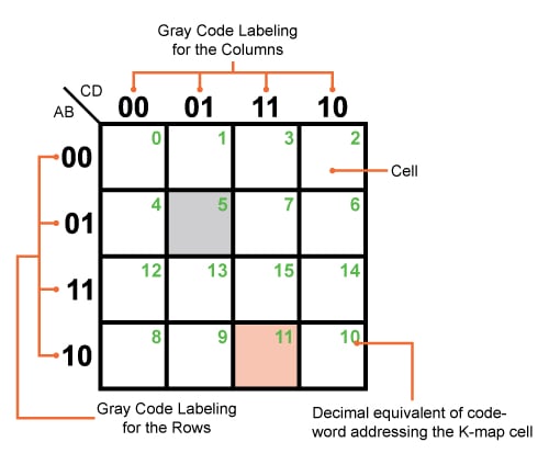
Figure 1. A typical but empty Karnaugh map with 16 cells
Here the rows and the columns of the K-map are labeled using a 2-bit Gray code, shown in the figure, which assigns a definite address for each of its cells.
For example, the grey-colored cell of the K-map shown can be addressed using the code-word "0101" which is equivalent to 5 in decimal (shown as the green number in the figure) and corresponds to the input variable combination A̅BC̅D or A+B̅+C+D̅, depending on whether the input-output relationship is expressed in SOP (sum of products) form or POS (product of sums) form, respectively.
Similarly, AB̅CD or A̅+B+C̅+D̅ refers to the Gray code-word of "1011", equivalent to 11 in decimal (again, shown in green in the figure), which in turn means that we are addressing the pink-colored K-map cell in the figure.
K-Map Simplification Technique
With this general idea of K-maps, let us now move on to the procedure employed in designing an optimal (in terms of the number of logic gates used to realize the logic) digital system. We'll start with a given problem statement.
Example 1:
Design a digital system whose output is defined as logically low if the 4-bit input binary number is a multiple of 3; otherwise, the output will be logically high. The output is defined if and only if the input binary number is greater than 2.
Step 1: Truth Table / Canonical Expression Leading to Min- or Max-Terms
The first step in designing any digital system is to have a clear idea of the variables involved in the process, along with their state values. Further, depending on the problem statement, we have to arrive at the number of output variables and their values for each and every combination of the input literals, which can be conveniently represented in the form of a truth table.
In the given example:
- The number of input variables = 4, which we will call A, B, C, and D.
- The number of output variables = 1, which we will call Y.
Where:
- Y = "Don't Care," if the input number is less than 3 (orange entries in the truth table)
- Y = 0, if the input number is an integral multiple of 3 (green entries in the truth table)
- Y = 1, if the input number is not an integral multiple of 3 (blue entries in the truth table)
Table 1. Truth table
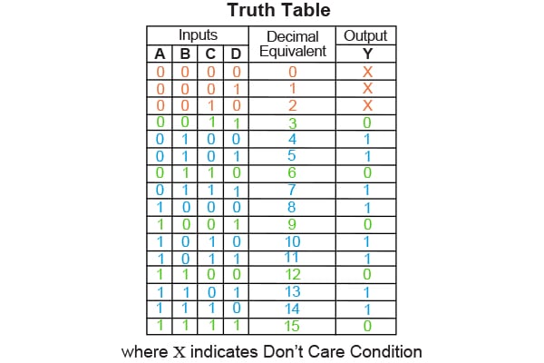
Note that, in addition to the input and output columns, the truth table also has a column that gives the decimal equivalent of the input binary combination, which makes it easy for us to arrive at the minterm or maxterm expansion for the given problem. Thus for the given example:
- Minterm expansion will be ∑m(4,5,7,8,10,11,13,14) + ∑d (0,1,2)
- Maxterm expansion will be ∏M(3,6,9,12,15) · ∏D (0,1,2)
However, sometimes the logical expression which is to be simplified might be directly given in terms of SOP or POS forms. In this case, the requirement for the truth table can be overlooked provided that we express the given expression in its canonical form, from which the corresponding minterms or maxterms can be obtained.
Step 2: Select and Populate K-Map
From Step 1, we know the number of input variables involved in the logical expression from which the size of the K-map required will be decided. Further, we also know the number of such K-maps required to design the desired system as the number of output variables would also be known definitely. This means, that for the example considered, we require a single (due to one output variable) K-map with 16 cells (as there are four input variables).
Next, we have to fill the K-map cells with one for each minterm, zero for each maxterm, and X for "Don't Care" terms. The procedure is to be repeated for every single output variable. For this example, we get the K-map as shown in Figure 2.
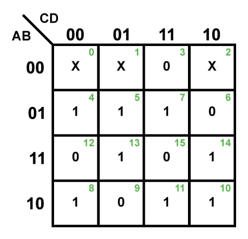
Figure 2. A completely filled 4-variable K-map
Step 3: Form the Groups
K-map simplification can also be referred to as the "simplification by grouping" technique as it solely relies on the formation of clusters. That is, the main aim of the entire process is to gather together as many ones (for SOP solution) or zeros (for POS solution) under one roof for each of the output variables in the problem stated. However, while doing so, we have to strictly abide by certain rules and regulations:
- The process has to be initiated by grouping the bits which lie in adjacent cells such that the group formed contains the maximum number of selected bits. This means that for an n-variable K-map with 2n cells, try to group for 2n cells first, then for 2n-1 cells, next for 2n-2 cells, and so on until the “group” contains only 20 cells, i.e., isolated bits (if any). Note that the number of cells in the group must be equal to an integer power to 2, i.e., 1, 2, 4, 8. . . .
- The procedure must be applied for all adjacent cells of the K-map, even when they appear to be not adjacent—the top row is considered to be adjacent to the bottom row and the rightmost column is considered to be adjacent to the leftmost column as if the K-map wraps around from top to bottom and right to left. For example, Group 1 of SOP form solution in Table 2.
- A bit appearing in one group can be repeated in another group provided that this leads to an increase in the resulting group size. For example, cell 5 is repeated in both Group 3 and 4 in the SOP form solution of Table 2 as it results in forming a group with two cells instead of a group with just one cell.
- "Don’t Care" conditions should be considered for the grouping activity if and only if they help obtain a larger group. Otherwise, they are to be neglected. Here the "Don't Care" terms in cells 0 and 1 are considered to create Group 2 of SOP solution form as it results in a group with four cells instead of just two.
Table 2.
| SOP Form Solution | POS Form Solution | ||||
| Number of groups having 16 cells | 0 | 0 | |||
| Number of groups having 8 cells | 0 | 0 | |||
| Number of groups having 4 cells (Blue Enclosures in Figure 3) | 2 | Group 1 (Cells 0,2,8,10) | 1 | Group 1 (Cells 0,1,2,3) | |
| Group 2 (Cells 0,1,4,5) | |||||
| Number of groups having 2 cells (Orange Enclosures in Figure 3) | 4 | Group 3 (Cells 5,7) | Group 4 (Cells 5,13) | 2 | Group 2 (Cells 1,9) |
| Group 5 (Cells 10,11) | Group 6 (Cells 10,14) | Group 3 (Cells 2,6) | |||
| Number of groups having 1 cell (Green Enclosures in Figure 3) | 0 | 2 | Group 4 (Cell 12) | ||
| Group 5 (Cell 15) | |||||
Thus, for the example considered, the K-map showing the groups can be obtained as given in Figure 3 whose information is summarized in Table 1.
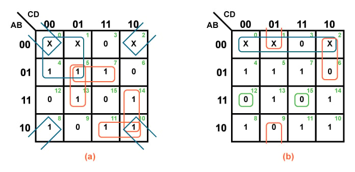
Figure 3. K-maps grouped for (a) SOP solution and (b) POS solution
Step 4: Simplified Logical Expression
For each of the resulting groups, we have to obtain the corresponding logical expression for the input variables. This can be done by expressing the bits which are common amongst the Gray code-words which represent the cells contained within the considered group. Another way to describe the process of obtaining the simplified logical expression for a group is to eliminate the variable(s) for which the corresponding bits appear within the group as both 0 and 1.
Finally, all these group-wise logical expressions need to be combined appropriately to form the simplified Boolean equation for the output variable. The same procedure must be repeated for every output variable of the given problem.
For instance, in the example considered, the logical term for Group 2 of the SOP form solution is obtained as A̅C̅. This is because this group has 0 as the common Gray code-word bit both along its rows as well as its columns, highlighted in Figure 4(a). This gives us the literals A̅ and C̅.
Similarly, in the case of Group 1 of POS form solution, we can obtain the logical expression as A+B. This is because the group has the common Gray code-words as 0,0 along its row only (no code-word bits are common along its columns) which correspond to the input variables A and B.
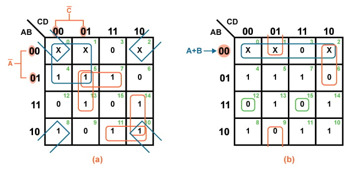
Figure 4. K-map simplification technique for (a) SOP solution and (b) POS solution
Following this same process, we can obtain the logical terms corresponding to each of the groups to finally form the logical expression for the particular output, as shown in Table 3.
Table 3.
| SOP Form Solution | POS Form Solution | ||
| Groups | Logical Expression | Groups | Logical Expression |
| Group 1 | B̅D̅ | Group 1 | A+B |
| Group 2 | A̅C̅ | Group 2 | B+C+D̅ |
| Group 3 | A̅BD | Group 3 | A+C̅+D |
| Group 4 | BC̅D | Group 4 | A̅+B̅+C+D |
| Group 5 | AB̅C | Group 5 | A̅+B̅+C̅+D̅ |
| Group 6 | ACD̅ | ||
| Thus, Y = B̅D̅ + A̅C̅ + A̅BD + BC̅D + AB̅C + ACD̅ | Thus, Y = (A+B) (B+C+D̅) (A+C̅+D) (A̅+B̅+C+D) (A̅+B̅+C̅+D̅) | ||
Step 5: System Design
Having obtained the simplified logical expression, we can decide on the type and the number of gates required to realize the expected logic for every output bit, which further results in the complete design of the desired system.
Thus, the digital system corresponding to SOP and POS forms of solution for the given example can be designed using the basic gates like NOT, AND, and OR as shown in Figure 5(a) and 5(b).
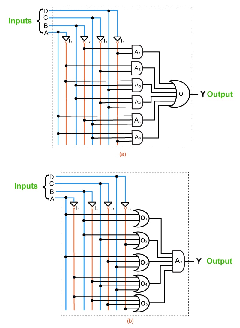
Figure 5. Digital system corresponding to (a) SOP form of solution and (b) POS form of solution
Now that we've analyzed each step for Example 1 let's practice by applying them to two more examples.
Example 2:
Design a full adder by obtaining the simplified expressions for the sum and carry outputs in POS form.
Step 1:
- Number of input variables = 3
- Number of output variables = 2
Table 4.
| Inputs | Decimal Equivalent | Outputs | |||
| A | B | Ci | S | Co | |
| 0 | 0 | 0 | 0 | 0 | 0 |
| 0 | 0 | 1 | 1 | 1 | 0 |
| 0 | 1 | 0 | 2 | 1 | 0 |
| 0 | 1 | 1 | 3 | 0 | 1 |
| 1 | 0 | 0 | 4 | 1 | 0 |
| 1 | 0 | 1 | 5 | 0 | 1 |
| 1 | 1 | 0 | 6 | 0 | 1 |
| 1 | 1 | 1 | 7 | 1 | 1 |
Maxterm expansion for S = ∏M (0,3,5,6)
Maxterm expansion for Co = ∏M (0,1,2,4)
Steps 2 and 3:
- Number of K-maps required = 2
- Each K-map should have 8 cells in it.
Thus we get:
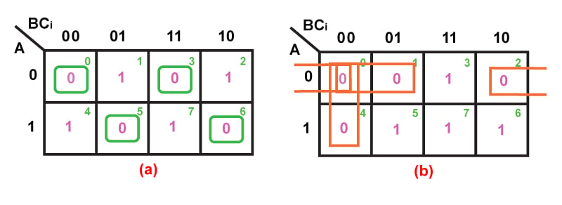
Figure 6. K-map simplification for full adder (a) sum output and (b) carry output
Table 5.
| Sum Output, S | Carry Output, Co | ||||||
| Groups with 8 cells | Nil | Nil | |||||
| Groups with 4 cells | Nil | Nil | |||||
| Groups with 2 cells (Orange Enclosures in Figure 6) |
Nil | 3 | Group 1 (Cells 0,1) | Group 2 (Cells 0,2) | |||
| Group 3 (Cells 0,4) | |||||||
| Groups with 1 cell (Green Enclosures in Figure 6) |
4 |
Group 1 (Cell 0) |
Group 2 (Cell 3) | Nil | |||
| Group 3 (Cell 5) | Group 4 (Cell 6) | ||||||
Step 4:
Table 6.
| Groups | Sum Output, S | Carry Output, Co |
| Group 1 | A + B + Ci | A + B |
| Group 2 | A + B̅ + C̅i | A + Ci |
| Group 3 | A̅ + B + C̅i | B + Ci |
| Group 4 | A̅ + B̅ + Ci | |
| S = (A + B + Ci) (A + B̅ + C̅i) (A̅ + B + C̅i) (A̅ + B̅ + Ci) | Co = (A + B) (A + Ci) (B + Ci) |
Step 5:
The digital system designed to realize the full adder in terms of sum and carry outputs (in POS form) is shown by Figure 7:
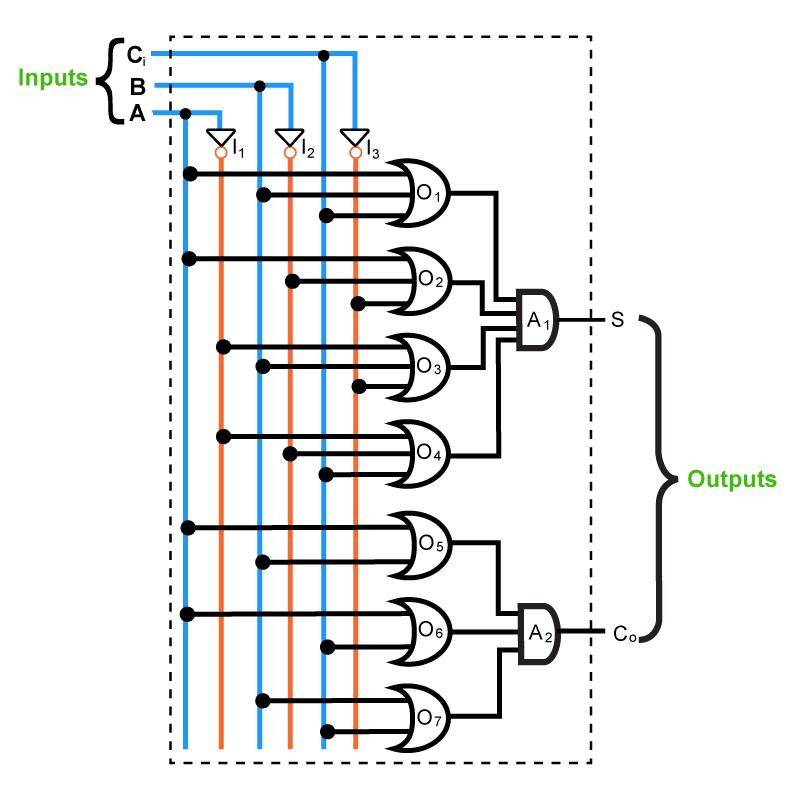
Figure 7. Full adder circuit
Example 3:
Simplify the Boolean expression f (A,B,C,D,E) = ∑m (0,3,4,7,8,12,14,16,19,20,23,24,26,28)
Step 1:
- Number of input variables = 5
- Number of output variables = 1
- Minterm expansion of the output is given as f (A,B,C,D,E) = ∑m (0,3,4,7,8,12,14,16,19,20,23,24,26,28)
Steps 2, 3, and 4:
- Number of K-maps required = 1
- Each K-map should have 32 cells in it.
Thus we get:
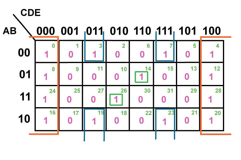
Figure 8: Grouped 32-cell K-map
Table 7.
| Number of Groups with 32 cells | Nil | |||
| Number of Groups with 16 cells | Nil | |||
| Number of Groups with 8 cells (Orange Enclosures in Figure 8) | 1 | Group 1 (Cells 0,4,8,12,16,20,24,28) | D̅E̅ | |
| Number of Groups with 4 cells (Blue Enclosures in Figure 8) | 1 | Group 2 (Cells 3,7,19,23) | B̅DE | |
| Number of Groups with 2 cells | Nil | |||
| Number of Groups with 1 cell (Green Enclosures in Figure 8) | 2 | Group 3 (Cell 14) | A̅BCDE̅ | |
| Group 4 (Cell 26) | ABC̅DE̅ | |||
| Thus, f (A,B,C,D,E) = D̅E̅ + B̅DE + A̅BCDE̅ + ABC̅DE̅ | ||||
Step 5:
The digital system corresponding to the function given is obtained as shown in Figure 9:
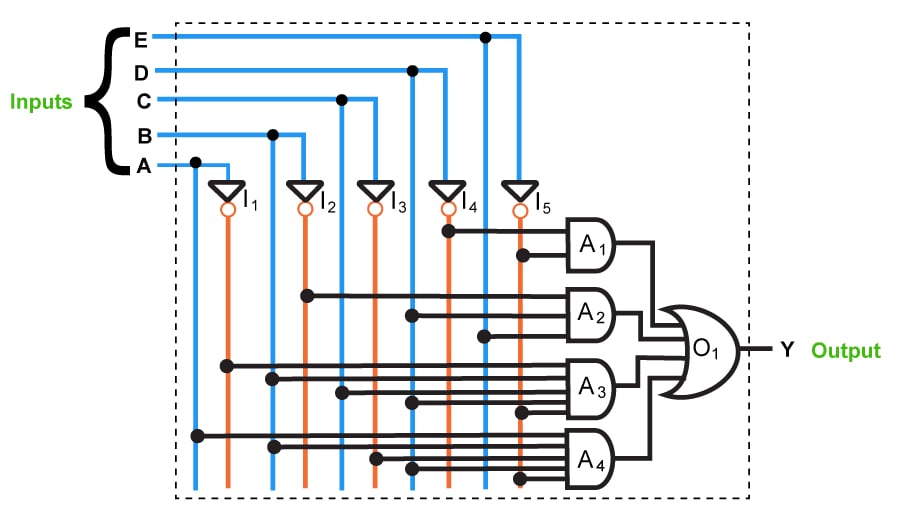
Figure 9. 5-variable K-map for the function shown in Example 3
Advantages of K-Maps
- The K-map simplification technique is simpler and less error-prone compared to the method of solving the logical expressions using Boolean laws.
- It prevents the need to remember each and every Boolean algebraic theorem.
- It involves fewer steps than the algebraic minimization technique to arrive at a simplified expression.
- K-map simplification technique always results in minimum expression if carried out properly.
Disadvantages of K-Maps
- As the number of variables in the logical expression increases, the K-map simplification process becomes complicated.
- The minimum logical expression arrived at by using the K-map simplification procedure may or may not be unique depending on the choices made while forming the groups. For example, for the output variable Y shown by the K-map in Figure 10, we can obtain two different but accurate logical expressions. The variation in the solution obtained is observed in the third term, which may be either B̅C̅ or AC̅ (highlighted in Figure 10). This difference depends on whether one chooses to group the cells (0,4) or (4,6) to form a two-celled group to cover the one found in the K-map cell numbered 4.
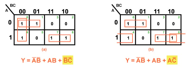
Figure 10. K-map with a non-unique solution
Conclusion
Having analyzed the structure of K-maps, we may arrive at the conclusion that the K-map simplification process is an effective reduction technique when dealing with logical expressions which contain around three to six input variables.
Related Content


Very interesting detailed discussion.
An alternative for the inputs.noOf() bit memory - in programming - such may turn out more optimal solution than complex nested comparison statements as : address = source bits , data = no. of bits required for output—(which however makes the code difficult to be grasped at debugging stage)—i intended to use such for system state/status bits derived/triggered evt.-s and did use such in output format filter . . . long ago
I would be very interested to know how six-input variable K-Maps work… I have been playing with K-Maps to simplify logic for thirty years and never seen one.