 Facebook
 Google
 GitHub
 Linkedin
Karnaugh Maps, Truth Tables, and Boolean Expressions
Who Developed the Karnaugh Map?
Maurice Karnaugh, a telecommunications engineer, developed the Karnaugh map at Bell Labs in 1953 while designing digital logic based telephone switching circuits.
The Use of Karnaugh Map
Now that we have developed the Karnaugh map with the aid of Venn diagrams, let’s put it to use. Karnaugh maps reduce logic functions more quickly and easily compared to Boolean algebra. By reduce we mean simplify, reducing the number of gates and inputs.
We like to simplify logic to a lowest cost form to save costs by elimination of components. We define lowest cost as being the lowest number of gates with the lowest number of inputs per gate.
Given a choice, most students do logic simplification with Karnaugh maps rather than Boolean algebra once they learn this tool.
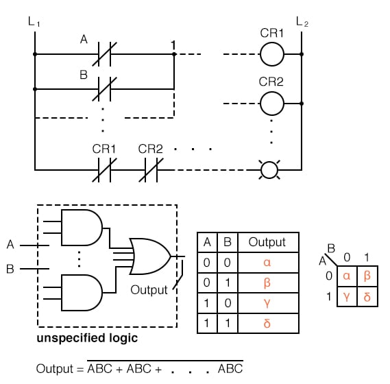
We show five individual items above, which are just different ways of representing the same thing: an arbitrary 2-input digital logic function. First is relay ladder logic, then logic gates, a truth table, a Karnaugh map, and a Boolean equation.
The point is that any of these are equivalent. Two inputs A and B can take on values of either 0 or 1, high or low, open or closed, True or False, as the case may be. There are 22 = 4 combinations of inputs producing an output. This is applicable to all five examples.
These four outputs may be observed on a lamp in the relay ladder logic, on a logic probe on the gate diagram. These outputs may be recorded in the truth table, or in the Karnaugh map. Look at the Karnaugh map as being a rearranged truth table.
The Output of the Boolean equation may be computed by the laws of Boolean algebra and transfered to the truth table or Karnaugh map.
Which of the five equivalent logic descriptions should we use? The one which is most useful for the task to be accomplished.
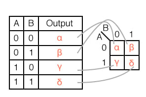
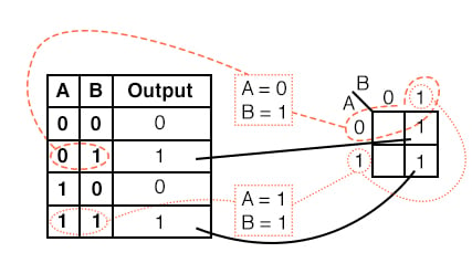
The outputs of a truth table correspond on a one-to-one basis to Karnaugh map entries. Starting at the top of the truth table, the A=0, B=0 inputs produce an output α.
Note that this same output α is found in the Karnaugh map at the A=0, B=0 cell address, upper left corner of K-map where the A=0 row and B=0 column intersect. The other truth table outputs β, χ, δ from inputs AB=01, 10, 11 are found at corresponding K-map locations.
Below, we show the adjacent 2-cell regions in the 2-variable K-map with the aid of previous rectangular Venn diagram like Boolean regions.
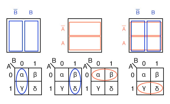
Cells α and χ are adjacent in the K-map as ellipses in the left most K-map below. Referring to the previous truth table, this is not the case. There is another truth table entry (β) between them. Which brings us to the whole point of the organizing the K-map into a square array, cells with any Boolean variables in common need to be close to one another so as to present a pattern that jumps out at us.
For cells α and χ they have the Boolean variable B’ in common. We know this because B=0 (same as B’) for the column above cells α and χ. Compare this to the square Venn diagram above the K-map.
A similar line of reasoning shows that β and δ have Boolean B (B=1) in common. Then, α and β have Boolean A’ (A=0) in common. Finally, χ and δ have Boolean A (A=1) in common. Compare the last two maps to the middle square Venn diagram.
To summarize, we are looking for commonality of Boolean variables among cells. The Karnaugh map is organized so that we may see that commonality. Let’s try some examples.
Examples
Example:
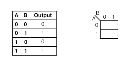
Transfer the contents of the truth table to the Karnaugh map above.
Solution:
The truth table contains two 1s. the K- map must have both of them. locate the first 1 in the 2nd row of the truth table above.
- note the truth table AB address
- locate the cell in the K-map having the same address
- place a 1 in that cell
Repeat the process for the 1 in the last line of the truth table.
Example:
For the Karnaugh map in the above problem, write the Boolean expression. Solution is below.
Solution:
Look for adjacent cells, that is, above or to the side of a cell. Diagonal cells are not adjacent. Adjacent cells will have one or more Boolean variables in common.
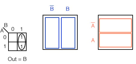
- Group (circle) the two 1s in the column
- Find the variable(s) top and/or side which are the same for the group, Write this as the Boolean result. It is B in our case.
- Ignore variable(s) which are not the same for a cell group. In our case A varies, is both 1 and 0, ignore Boolean A.
- Ignore any variable not associated with cells containing 1s. B’ has no ones under it. Ignore B’
- Result Out = B
This might be easier to see by comparing to the Venn diagrams to the right, specifically the B column.
Example:
Write the Boolean expression for the Karnaugh map below.
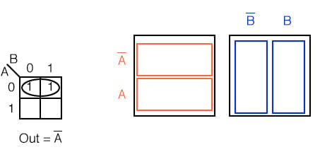
Solution: (above)
- Group (circle) the two 1’s in the row
- Find the variable(s) which are the same for the group, Out = A’
Example:
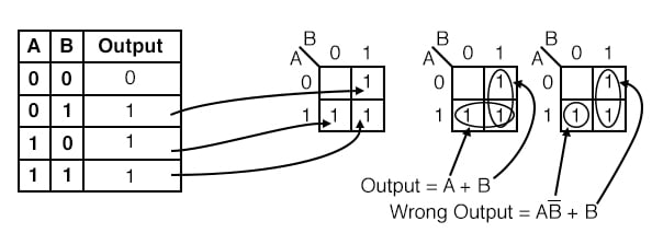
For the Truth table below, transfer the outputs to the Karnaugh, then write the Boolean expression for the result.
Solution:
Transfer the 1s from the locations in the Truth table to the corresponding locations in the K-map.
- Group (circle) the two 1’s in the column under B=1
- Group (circle) the two 1’s in the row right of A=1
- Write product term for first group = B
- Write product term for second group = A
- Write Sum-Of-Products of above two terms Output = A+B
The solution of the K-map in the middle is the simplest or lowest cost solution. A less desirable solution is at far right. After grouping the two 1s, we make the mistake of forming a group of 1-cell. The reason that this is not desirable is that:
- The single cell has a product term of AB’
- The corresponding solution is Output = AB’ + B
- This is not the simplest solution
The way to pick up this single 1 is to form a group of two with the 1 to the right of it as shown in the lower line of the middle K-map, even though this 1 has already been included in the column group (B). We are allowed to re-use cells in order to form larger groups. In fact, it is desirable because it leads to a simpler result.
We need to point out that either of the above solutions, Output or Wrong Output, are logically correct. Both circuits yield the same output. It is a matter of the former circuit being the lowest cost solution.
Example:
Fill in the Karnaugh map for the Boolean expression below, then write the Boolean expression for the result.
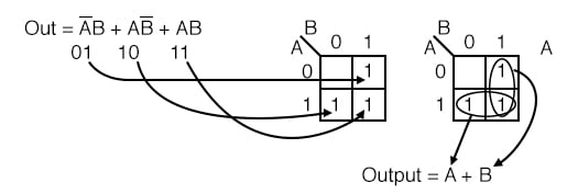
Solution: (above)
The Boolean expression has three product terms. There will be a 1 entered for each product term. Though, in general, the number of 1s per product term varies with the number of variables in the product term compared to the size of the K-map.
The product term is the address of the cell where the 1 is entered. The first product term, A’B, corresponds to the 01 cell in the map. A 1 is entered in this cell. The other two P-terms are entered for a total of three 1s
Next, proceed with grouping and extracting the simplified result as in the previous truth table problem.
Example:
Simplify the logic diagram below.
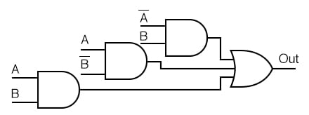
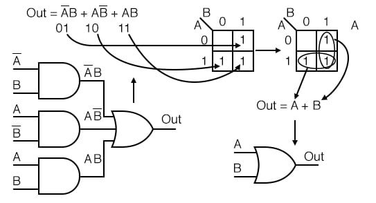
Solution: (Figure below)
- Write the Boolean expression for the original logic diagram as shown below
- Transfer the product terms to the Karnaugh map
- Form groups of cells as in previous examples
- Write Boolean expression for groups as in previous examples
- Draw simplified logic diagram
Example: Simplify the logic diagram below.
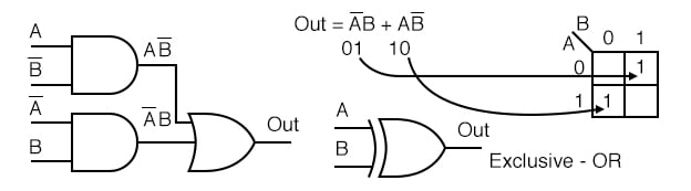
Solution:
- Write the Boolean expression for the original logic diagram shown above
- Transfer the product terms to the Karnaugh map.
- It is not possible to form groups.
- No simplification is possible; leave it as it is.
No logic simplification is possible for the above diagram. This sometimes happens. Neither the methods of Karnaugh maps nor Boolean algebra can simplify this logic further.
We show an Exclusive-OR schematic symbol above; however, this is not a logical simplification. It just makes a schematic diagram look nicer.
Since it is not possible to simplify the Exclusive-OR logic and it is widely used, it is provided by manufacturers as a basic integrated circuit (7486).
RELATED WORKSHEETS:


Great article but you use different greek letters in your diagrams vs explanation. Gamma vs Chi?