 Facebook
 Google
 GitHub
 Linkedin
Don’t Care Cells in the Karnaugh Map
Up to this point we have considered logic reduction problems where the input conditions were completely specified. That is, a 3-variable truth table or Karnaugh map had 2n = 23 or 8-entries, a full table or map.
It is not always necessary to fill in the complete truth table for some real-world problems. We may have a choice to not fill in the complete table.
For example, when dealing with BCD (Binary Coded Decimal) numbers encoded as four bits, we may not care about any codes above the BCD range of (0, 1, 2…9). The 4-bit binary codes for the hexadecimal numbers (Ah, Bh, Ch, Eh, Fh) are not valid BCD codes.
Thus, we do not have to fill in those codes at the end of a truth table, or K-map, if we do not care to.
We would not normally care to fill in those codes because those codes (1010, 1011, 1100, 1101, 1110, 1111) will never exist as long as we are dealing only with BCD encoded numbers. These six invalid codes are don’t cares as far as we are concerned.
That is, we do not care what output our logic circuit produces for these don’t cares.
Don’t Cares
Don’t cares in a Karnaugh map, or truth table, may be either 1s or 0s, as long as we don’t care what the output is for an input condition we never expect to see. We plot these cells with an asterisk, *, among the normal 1s and 0s.
When forming groups of cells, treat the don’t care cell as either a 1 or a 0, or ignore the don’t cares.
This is helpful if it allows us to form a larger group than would otherwise be possible without the don’t cares. There is no requirement to group all or any of the don’t cares.
Only use them in a group if it simplifies the logic.
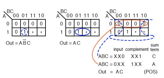
Above is an example of a logic function where the desired output is 1 for input ABC = 101 over the range from 000 to 101. We do not care what the output is for the other possible inputs (110, 111). Map those two as don’t cares. We show two solutions.
The solution on the right Out = AB’C is the more complex solution since we did not use the don’t care cells. The solution in the middle, Out=AC, is less complex because we grouped a don’t care cell with the single 1 to form a group of two.
The third solution, a Product-Of-Sums on the right, results from grouping a don’t care with three zeros forming a group of four 0s. This is the same, less complex, Out=AC.
We have illustrated that the don’t care cells may be used as either 1s or 0s, whichever is useful.

The electronics class of Lightning State College has been asked to build the lamp logic for a stationary bicycle exhibit at the local science museum. As a rider increases his pedaling speed, lamps will light on a bar graph display.
No lamps will light for no motion. As speed increases, the lower lamp, L1 lights, then L1 and L2, then, L1, L2, and L3, until all lamps light at the highest speed. Once all the lamps illuminate, no further increase in speed will have any effect on the display.
A small DC generator coupled to the bicycle tire outputs a voltage proportional to speed. It drives a tachometer board which limits the voltage at the high end of speed where all lamps light. No further increase in speed can increase the voltage beyond this level.
This is crucial because the downstream A to D (Analog to Digital) converter puts out a 3-bit code, ABC, 23 or 8-codes, but we only have five lamps. A is the most significant bit, C the least significant bit.
The lamp logic needs to respond to the six codes out of the A to D. For ABC=000, no motion, no lamps light. For the five codes (001 to 101) lamps L1, L1&L2, L1&L2&L3, up to all lamps will light, as speed, voltage, and the A to D code (ABC) increases.
We do not care about the response to input codes (110, 111) because these codes will never come out of the A to D due to the limiting in the tachometer block. We need to design five logic circuits to drive the five lamps.

Since, none of the lamps light for ABC=000 out of the A to D, enter a 0 in all K-maps for cell ABC=000. Since we don’t care about the never to be encountered codes (110, 111), enter asterisks into those two cells in all five K-maps.
Lamp L5 will only light for code ABC=101. Enter a 1 in that cell and five 0s into the remaining empty cells of L5 K-map.
L4 will light initially for code ABC=100, and will remain illuminated for any code greater, ABC=101, because all lamps below L5 will light when L5 lights. Enter 1s into cells 100 and 101 of the L4 map so that it will light for those codes. Four 0‘s fill the remaining L4 cells
L3 will initially light for code ABC=011. It will also light whenever L5 and L4 illuminate. Enter three 1s into cells 011, 100, 101 for L3 map. Fill three 0s into the remaining L3 cells.
L2 lights for ABC=010 and codes greater. Fill 1s into cells 010, 011, 100, 101, and two 0s in the remaining cells.
The only time L1 is not lighted is for no motion. There is already a 0 in cell ABC=000. All the other five cells receive 1s.
Group the 1‘s as shown above, using don’t cares whenever a larger group results. The L1 map shows three product terms, corresponding to three groups of 4-cells.
We used both don’t cares in two of the groups and one don’t care on the third group. The don’t cares allowed us to form groups of four.
In a similar manner, the L2 and L4 maps both produce groups of 4-cells with the aid of the don’t care cells. The L4 reduction is striking in that the L4 lamp is controlled by the most significant bit from the A to D converter, L5=A.
No logic gates are required for lamp L4. In the L3 and L5 maps, single cells form groups of two with don’t care cells. In all five maps, the reduced Boolean equation is less complex than without the don’t cares.

The gate diagram for the circuit is above. The outputs of the five K-map equations drive inverters. Note that the L1 OR gate is not a 3-input gate but a 2-input gate having inputs (A+B), C, outputting A+B+C The open collector inverters, 7406, are desirable for driving LEDs, though, not part of the K-map logic design.
The output of an open collector gate or inverter is open-circuited at the collector internal to the integrated circuit package so that all collector current may flow through an external load. An active high into any of the inverters pulls the output low, drawing current through the LED and the current limiting resistor.
The LEDs would likely be part of a solid-state relay driving 120 VAC lamps for a museum exhibit, not shown here.
RELATED WORKSHEETS:


There’s a typo in the article. For the L5 circuits, the 100 cell should be 0, since the L5 lamp only lights up for code 101.