Facebook
 Google
 GitHub
 Linkedin
DC Lab - Potentiometer as a Rheostat
Project Overview
A variable resistor is known as a rheostat, but potentiometers can be made to function as rheostats quite easily. In this project, you learn how to use a potentiometer to control the speed of a motor, as illustrated in Figure 1.
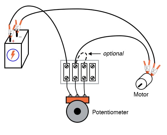
Figure 1. Using a potentiometer as a rheostat to control motor speed.
Learning Objectives
- How to use a rheostat
- Wiring a potentiometer as a rheostat
- Simple motor speed control
- Understand why to use a voltmeter instead of an ammeter to verify a continuous circuit
Parts and Materials
- 6 V battery
- Potentiometer, single turn, ≤5 kΩ, linear taper
- Small “hobby” motor, permanent-magnet type
Instructions
In the first section of this experiment, we will review the operation of a potentiometer as a variable resistance (rheostat) before using it for motor speed control.
Measure the Changing Potentiometer Resistance Across Different Terminals
Potentiometers find their most sophisticated application as voltage dividers, where shaft position determines a specific voltage division ratio. However, there are applications where we don’t necessarily need a variable voltage divider but merely a variable resistor: a two-terminal device. Technically, a variable resistor is known as a rheostat.
Step 1: In its simplest configuration, a potentiometer may be used as a rheostat by simply using the wiper terminal and one of the other terminals, as illustrated in Figure 2.
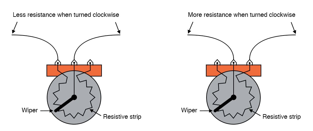
Figure 2. The changing resistance of a potentiometer as a function of the terminals.
The third terminal is left unconnected and unused. First, measure the resistance of the potentiometer across the wiper terminal and one of the end terminals, as shown on the left side of Figure 2. Note how the resistance changes as you adjust the potentiometer wiper both clockwise and counter-clockwise. Additionally, you should notice that moving the potentiometer control in the direction that brings the wiper closer to the second terminal in use results in a lower resistance.
Step 2: Repeat the process of Step 1, but use the other end terminal in conjunction with the wiper terminal, as illustrated on the right side of Figure 2. The direction of motion required to increase or decrease resistance should be opposite from what you determined in Step 1. Why is that?
Step 3: Next, measure the resistance across the two outer terminals. This will result in no change in resistance as the potentiometer shaft is turned, as shown in Figure 3. In other words, it will no longer function as a variable resistance.
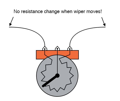
Figure 3. There is no resistance change across the outer potentiometer terminals as the wiper moves.
Controlling Motor Speed With a Potentiometer-based Rheostat
Step 4: Build the circuit, as shown in the circuit schematic of Figure 4 and the illustration of Figure 5, using just two terminals on the potentiometer. Keep in mind that one of the terminals must be the wiper.
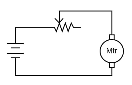
Figure 4. The schematic diagram for building the motor speed control circuit using a potentiometer.
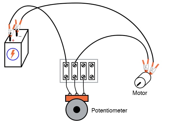
Figure 5. Illustration for building the motor speed control circuit using a potentiometer.
Step 5: Adjust the shaft position of the potentiometer and see how the motor speed may be controlled. If your potentiometer has high resistance (as measured between the two outer terminals), the motor might not move at all until the wiper is brought very close to the connected outer terminal. As you can see from this experiment, the motor speed may be made variable using a series-connected rheostat to change total circuit resistance and limit total current.
Step 6: Experiment with different terminal connections on the potentiometer (similar to Step 2 above), noting the changes in motor speed control as a function of the terminal connections.
Improving the Safety of the Potentiometer for Motor Speed Control
Step 7: When a potentiometer is used as a rheostat, the “unused” terminal is often connected to the wiper terminal, as illustrated in Figure 6.
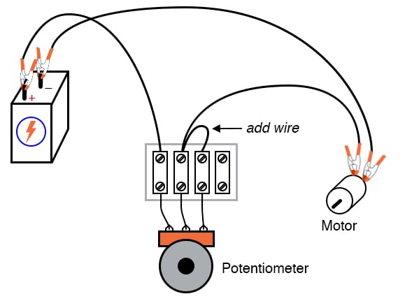
Figure 6. Adding an additional wiper connection to the potentiometer rheostat.
At first, this seems rather pointless, as it has no impact on resistance control. You may verify this fact for yourself by adding the extra wire, as noted in Figure 6, and comparing motor behavior before and after the change. Did it change? If the potentiometer is in good working order, this additional wire should make no difference whatsoever.
Step 8: However, if the wiper ever loses contact with the resistive strip inside the potentiometer, this connection ensures the circuit does not completely open. Therefore, there will still be a resistive path for current through the motor.
In some applications, this may be important. For example, old potentiometers tend to suffer from intermittent contact losses between the wiper and the resistive strip. If a circuit cannot tolerate the complete loss of continuity (infinite resistance) created by this condition, that “extra” wire provides a measure of protection by maintaining circuit continuity.
You can simulate a wiper contact “failure” by disconnecting the potentiometer’s middle terminal from the terminal strip, as illustrated in Figure 7.
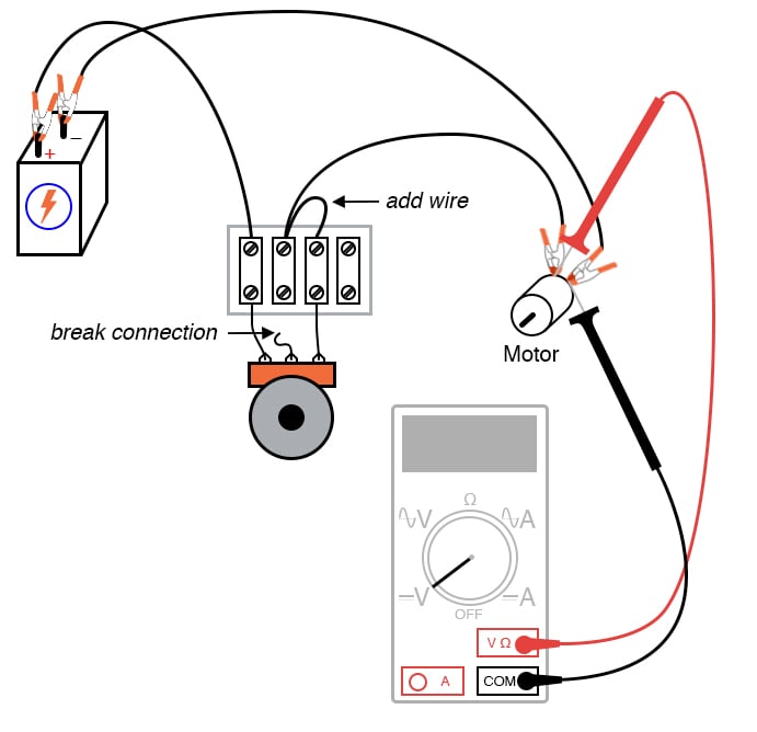
Figure 7. Simulating a potentiometer wiper failure.
From here, measure the voltage across the motor (also illustrated in Figure 7) to ensure there is still power getting to it, however small.
Measuring Motor Voltage is a Safer Alternative to Measuring Circuit Current
It would have been valid to measure the circuit current in Step 8 instead of the motor voltage to verify a completed circuit. However, this is a safer method because it does not involve breaking the circuit to insert an ammeter in series. Whenever an ammeter is used, there is a risk of causing a short circuit by connecting it across a substantial voltage source, possibly resulting in instrument damage or personal injury. Voltmeters lack this inherent safety risk. So, whenever a voltage measurement may be made instead of a current measurement to verify the same thing, it is the wiser choice.
Alternative Motor Control Techniques
This simple method of motor speed control using a rheostat is inefficient, resulting in substantial amounts of power being dissipated (wasted) by the rheostat. A much more efficient means of motor control relies on fast pulsing of power to the motor, using a high-speed switching device such as a transistor. This pulse width modulated signal is often driven by a dedicated timer in a microcontroller. A similar method of power control is used in household light dimmer switches. Unfortunately, these techniques are much too sophisticated to explore at this point in the experiments.
Related Content
Learn more about the fundamentals behind this project in the resources below.
Calculators:
Worksheets:
Textbook:
Resistor Guide:
Video Tutorials and Lectures:
- Series Circuits Part 1
- Series Circuits Part 2: Voltage Divider Equation
- Series Circuits Part 3: Series Voltage Sources