Facebook
 Google
 GitHub
 Linkedin
Pulse-width Modulation (PWM) Timers in Microcontrollers
This article is the second of a series on microcontroller timers. This article describes a more complex timer called the PWM or pulse-width modulation timer.
This article is the second of a series on microcontroller timers. The first article describes major features of most types of timers and covers periodic timers.
This article describes a more complex timer called the PWM or pulse-width modulation timer. If you are not familiar with the general operation of microcontroller timers, I recommend reading the first article before this one.
PWM timers are commonly used for motion control and dimming LEDs. Examples of these applications are included here.
PWM Duty Cycle
Duty cycle is the amount of time a digital signal is in the “active” state relative to the period of the signal. Duty cycle is usually given as a percentage.
For example, a perfect square wave with equal high time and low time has a duty cycle of 50%. Here is a diagram showing duty cycle in a general way.
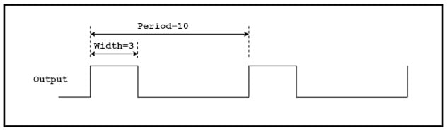
Figure 1. A representation of the concept of duty cycle
Duty Cycle Microcontroller Timer Calculation
Based on the example above, how do we calculate the duty cycle?
If active high, the duty cycle is
(Width ÷ Period) ✕ 100 = (3 ÷ 10) ✕ 100 = 30%
If we define the signal as active low, the duty cycle is 70%.
PWM Timer Overview
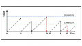
Here is a timing diagram of a typical PWM signal.
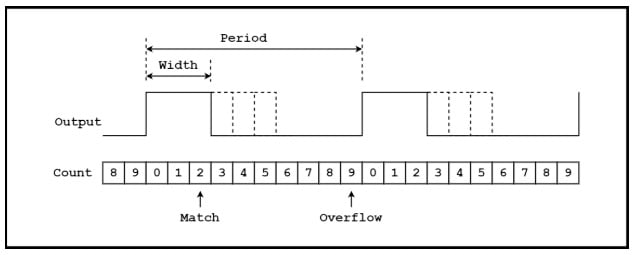
Figure 2. An example PWM timing diagram
A counter counts up from 0 to an “overflow” value in a modulus register. When the modulus is reached, the counter goes to 0 on the next clock. The modulus here is a value of 9 and the number of states for the counter is 9+1 or 10. The counting simply repeats for as long as the timer is enabled. The output of the counter goes to “Width” logic, which sets the output high when the counter overflows and sets the output low when the counter matches the Width register.
The width of the output pulse is changed “on the fly” by changing the value in the Width register. This action is indicated with the dotted lines.
As shown in the next diagram, period and pulse width are set by loading the appropriate value into a register. For the timing diagram above, the period register would contain a value of 9, and the width register would contain a value of 2.
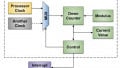
Here is a block diagram of a typical PWM timer.
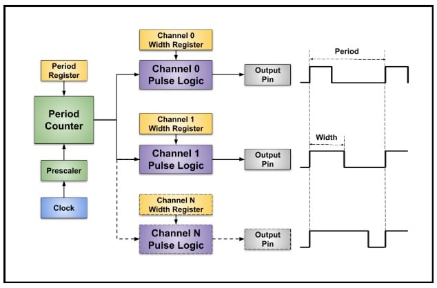
Figure 3. A PWM timer block diagram
A clock is divided down by a prescaler and applied to a period counter. The duration of the period counter is set with a modulus or period register. The output of the period counter goes to multiple “channels” of pulse width logic. The width of the pulse from each channel is independently controlled since each channel has a separate Width register.
Notice the period of all the channels are the same because they share the same period counter but the pulse widths are different.
PWM Motor Control
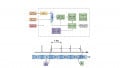
An important use of PWM timers is motor control. The diagram below shows a typical setup with the PWM signal going to a motor controller which controls a motor. (If you’d like to see PWM in action, take a look at AAC’s C-BISCUIT robot, which uses pulse-width modulation to control motor speed.)
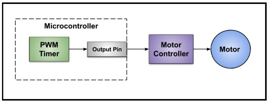
Figure 4. A simplified block diagram of a PWM setup
The timing diagram below shows an example where the direction and amount of torque is controlled with a PWM signal.
This timing is called “50% PWM” which means a 50% duty cycle produces no torque and duty cycles greater or less than 50% control the amount of torque in two directions.
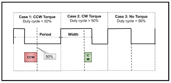
Figure 5. An example wherein two functions of torque are controlled by a PWM signal
Case 3 is 50% duty cycle and the motor does not move. Case 2 is a duty cycle greater than 50% and the motor moves clockwise with torque proportional to the amount the duty cycle is greater than 50%. Case 1 is a duty cycle less than 50% and the motor moves counterclockwise with torque proportional to the amount the duty cycle is less than 50%.
Servo Motor PWM Example
Another example is a servo motor, which changes the angle of a shaft according to the width of the pulse. For example, a 1.5 millisecond pulse sets the shaft to 0°. Changing the pulse width from 1.5 milliseconds to 1 millisecond rotates from 0° to -90° and from 1.5 milliseconds to 2 milliseconds goes from 0° to +90°.
I am currently working with a “continuous rotation servo motor”. The motor continuously rotates in either direction under control of a PWM signal. The direction and speed varies with the pulse width as shown in this diagram.
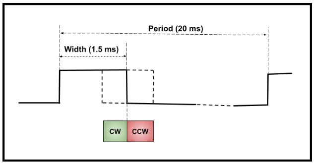
Figure 6. Varying speed and direction of a motor's rotation, as controlled by a PWM signal
The period is 20 milliseconds and an active high pulse controls the direction and speed. The motor does not move when the pulse width is 1.5 milliseconds. Going wider than 1.5 milliseconds increases the speed in the counterclockwise direction and going narrower than 1.5 milliseconds makes the motor go in the clockwise direction.
Controlling LED Intensity with a PWM Timer
Another example of using the duty cycle of a PWM timer is controlling the intensity of an LED. Here is the basic schematic:
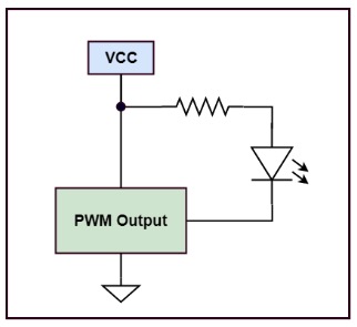
Figure 7. Basic schematic for an LED controlled by a PWM timer
The LED is on when the timer output is low and off when the output is high. The timer creates a rapidly changing output which turns the LED on and off fast enough so the eye averages the “on” time and perceives a change in intensity and not blinking on and off.
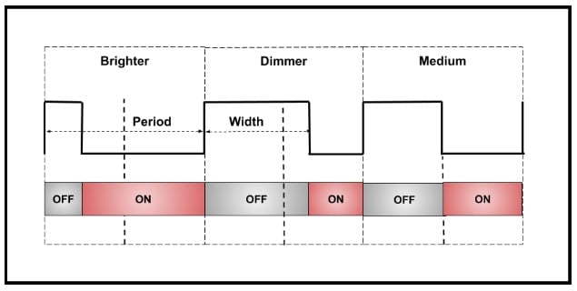
Figure 8. Three PWM-controlled LED cases for "brighter," "dimmer," and "medium" LEDs
The diagram shows three cases. The “brighter” case is low for most of the period and the LED appears brighter than the “dimmer” case which is low for a shorter time.
Timing Setup for a Servo Motor
The most complicated part of using a PWM timer is setting the timing parameters to meet the requirements of the external device. I think of a PWM timer as a type of digital-to-analog converter (DAC). (And actually, a PWM can be used as a DAC with some help from a low-pass filter.) A voltage-output DAC takes a digital value in and converts it to an analog output voltage. The smallest change in the analog output occurs when the digital value changes by one count.
For a PWM timer, the width of the output pulse is like the analog value. The smallest change in the width occurs when the value in the width register changes by one count. This smallest possible change in the output is called the output resolution.
For a PWM timer, the output resolution or smallest possible change in the period or width of the output pulse is one period of the clock going into the period counter.
For example, if the period of the clock into the period counter is 10 microseconds (a frequency of 100kHz), the timing resolution of the output period and pulse width is 10 microseconds.
In this section, I determine the timing parameters to control the “continuous rotation servo motor” described above. Look back to the timing diagram in Figure 6 above for reference.
Here is the information about the PWM timer needed to determine the timing.
- Clock frequency: 24 MHz
- Prescaler options: Divide by 1, 2, 4, 8, 16, 32, 64, or 128
- Period counter and Width register: 16 bits wide or 65,536 counts
Here are the requirements for the servo motor.
- PWM period: 20 milliseconds
- PWM pulse width for motor stopped: 1.5 milliseconds.
- PWM pulse width for max speed CCW: 2.0 milliseconds
- PWM pulse width for max speed CW: 1.0 milliseconds
Selecting a Prescaler Value
The first part of the setup is selecting a divide value for the prescaler.
If the value is too small (fast clock), the maximum PWM period using a 16-bit counter is too short. If the value is large (slow clock), the resolution of the timing is poor and there is coarse control. A good place to start is determining the highest possible frequency into the period counter, fPC, to give an output period of 20 milliseconds. If the input frequency is high, we’ll have to use a large count modulus to obtain the desired period. Let’s try a modulus of 60,000 and determine the period counter input frequency.
fPC = (0.02 / 60,000)-1 = 3,000,000 Hz = 3 MHz
The clock into the prescaler is 24 MHz. So, the prescaler divide value, P, is
P = ( 24MHz / 3MHz) = 8
Perfect! I can use a prescaler setting of divide by 8 and a period counter modulus of 60,000 for a PWM period of 20 milliseconds. Now we know the timing resolution for the output pulse. The timing resolution is the period of the 3 MHz clock or 0.333 microseconds.
A modulus of 60,000 is a lucky guess which matches nicely with one of the prescaler settings. Determining settings often requires a bit of “back and forth” between a counter modulus and prescaler settings to get close to an ideal period. Often, peripherals do not need an exact period and there is leeway in the timing.
Selecting Values for the Pulse Width Register
Let’s move on to selecting values for the pulse width register, W. The pulse width, tW, is given by
tW = W ✕ 0.333x10⁻⁶
W = tW / 0.333x10⁻⁶
Here is a table with the values for W for the specified motor settings.
| Motor Setting | Pulse Width (in seconds) | W |
|---|---|---|
| Stopped | 0.0015 |
4,500 |
| Max CW speed | 0.0020 | 6,000 |
| Max CCW speed | 0.0010 | 3,000 |
The value in the width register is varied from 3,000 to 6,000 for full control of the motor. Finally, one count is subtracted from the period and width values written to the registers to adjust for the extra “0” count.
Here are all the timer values:
- Clock frequency: 24 MHz
- Prescaler: Divide by 8
- Period counter modulus: 59,999
- Pulse width register for motor stopped: 4,499
- Pulse width register for max speed CW: 5,999
- Pulse width register for max speed CCW: 2,999
In practice, servo motors are usually not very precise and need calibration by adjusting these values. The values above give a “nominal” place to start. Also, subtracting one count is usually not necessary since this adjustment is taken into account by calibration.
Considering Control Resolution
There is one more thing to consider: Is the control resolution fine enough?
The number of counts from stopped to full speed in either direction is 1,500. So, the control resolution is one part in 1,500, i.e., less than 0.1%. This is very high resolution for a low-end servo motor, but high resolution may be needed for other types of motors.
Notice how the first step above looks for the smallest prescale. A higher frequency going into the period counter offers higher resolution.
Another way to look at this is using more counts in the period counter gives higher resolution.
Interrupts
Sometimes tight control between the PWM output and the software is important. An efficient way to synchronize the two is with interrupts (see the first article in this series for more information on interrupts).
PWM timers often have the option of producing an interrupt request when the period counter overflows and when the width logic sees a match (the end of an output pulse). If there are multiple channels, the interrupt service routine would typically read a register in the timer to find out which channel requested the interrupt.
What’s Next
The next article in the series describes a very interesting type of timer called a real-time clock or RTC. An RTC gives a microcontroller the important capability of accurately keeping the time of day and a calendar.