 Facebook
 Google
 GitHub
 Linkedin
Turn Your PWM into a DAC
If your microcontroller doesn’t have a digital-to-analog converter, you can make a passable replacement with nothing more than a pulse-width-modulated signal and a low-pass filter.
If your microcontroller doesn’t have a digital-to-analog converter, you can make a passable replacement with nothing more than a pulse-width-modulated signal and a low-pass filter.
Supporting Information
When You Lack a DAC
Even in this age of highly integrated mixed-signal integrated circuits, it is not uncommon to come across a microcontroller that does not include a digital-to-analog converter. Programmable logic is even more problematic in this respect; I have never heard of an FPGA or CPLD that has a DAC module. And even when a microcontroller does have a DAC, there may be only one or two channels—in contrast to integrated ADC peripherals, which usually incorporate a multiplexer that allows one ADC module to convert analog signals connected to several, or maybe even dozens, of port pins. So what are you supposed to do when you find a microcontroller that is perfect for your application in every way except that it doesn’t have an integrated DAC? Well, the most obvious option is to use an external DAC. A quick Digi-Key search indicates that you have at least a thousand to choose from, some of which cost less than a dollar and come in tiny SC70, MSOP, SOT, or DFN packages. But there are times when you really don’t want to add another chip to the design. Maybe your microcontroller doesn’t have the three unused pins you will need for SPI communication; maybe you are in a rush and don’t want to pay for overnight shipping; maybe you need six separate DAC outputs but don’t have enough board space for a six-channel device. In any event, if an external DAC is simply out of the question, you have an alternative.
PWM, Resistor, Capacitor
The bare minimum here is a resistor, a capacitor, and some sort of pulse-width-modulation functionality. You will certainly have no shortage of PWM capabilities if you’re using an FPGA or CPLD. For processors, I think that every microcontroller I’ve ever worked with included PWM hardware, but I suppose there must be some parts that don’t. So that’s the first thing to check—if your microcontroller doesn’t have PWM, you’re out of luck (unless you want to rig up some sort of bit-banging PWM routine, but seriously, if you’re in that boat just use an external DAC). Next, you need a way to low-pass filter the PWM signal. A basic single-pole RC filter could be fine if you don’t mind some ripple on the output, so if all you can fit into your board or budget is a resistor and capacitor, the PWM DAC is still a viable option. However, a better filter means a better DAC, and it might be worth your while to bring in an inductor or an op-amp so you can have two poles instead of one.
PWM–The Basics
You probably already know what pulse-width modulation is; nevertheless, we’ll briefly review the essential concepts to make sure that we have a solid foundation when we look at how exactly a low-pass filter turns a digital signal into a programmable analog voltage.
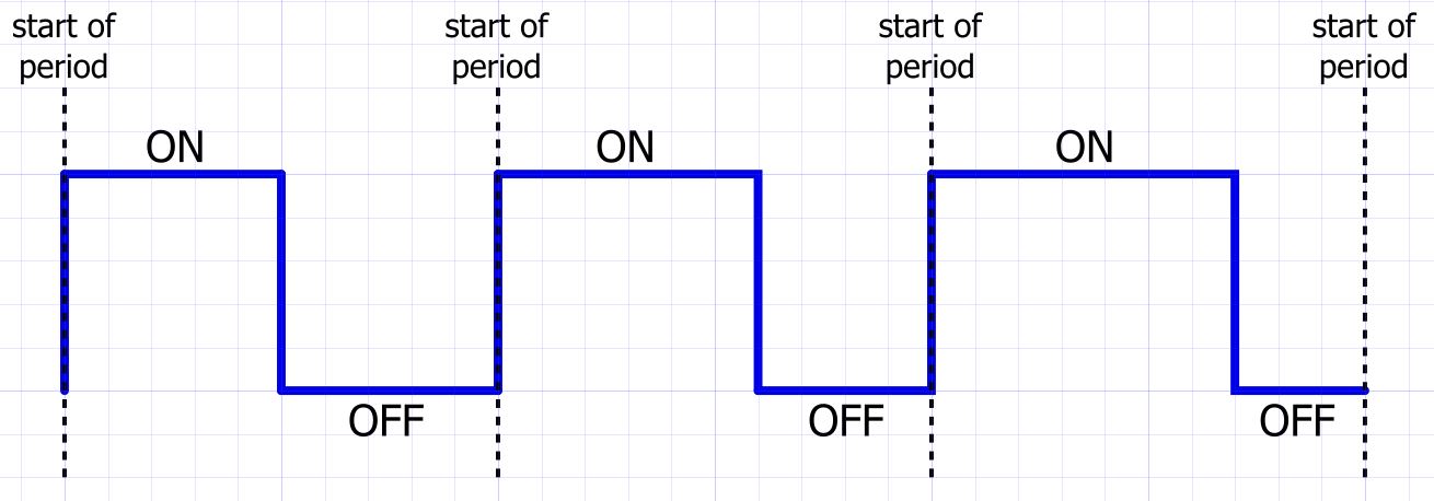
A typical digital clock signal is a sequence of periods in which the duration of the logic-high voltage is equal to the duration of the logic-low voltage. In contrast, a PWM signal is a sequence of periods in which the duration of the logic-high (or logic-low) voltage varies according to external conditions, and these variations can be used to transmit information. If you are familiar with radio circuitry, you know that information is transmitted by means of sinusoidal signals to which some type of modulation is applied. This situation is analogous to PWM functionality—instead of amplitude or frequency modulation we have pulse-width modulation. You may find it helpful to think in terms of this conceptual similarity: We all know that an analog audio signal can be transmitted from an antenna to a car radio by first modulating a carrier wave and then processing the received signal in a way that removes the carrier and recovers the original audio information. Likewise, we can generate a programmable analog voltage by pulse-width modulating a digital carrier wave then “transmitting” this modulated signal to a low-pass filter.
In the above diagram, logic high is identified as the “ON” or active state, and logic low is the “OFF” or inactive state. In the first period, the duration of the active state is equal to the duration of the inactive state. Then, for the next two periods, the active-state duration increases by one grid width; this means that the inactive-state duration must decrease by one grid width, because the PWM carrier frequency (and thus the PWM period) is constant. In the context of our PWM DAC, we don’t really need to know the absolute active and inactive durations; what matters is the ratio between the durations, which we discuss in terms of the PWM duty cycle:
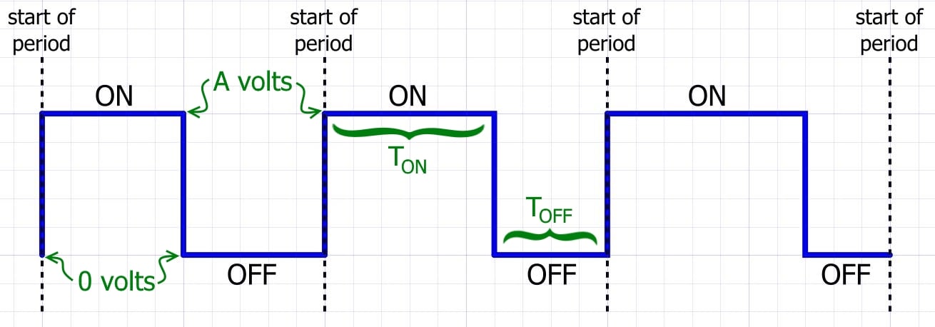
\[duty\ cycle=\frac{T_{ON}}{T_{ON}+T_{OFF}}\]
From Duty Cycle to Analog Voltage
The nominal DAC voltage observed at the output of the low-pass filter is determined by just two parameters, namely, the duty cycle and the PWM signal’s logic-high voltage; in the diagram, this logic-high voltage is denoted by A for “amplitude.” The relationship between duty cycle, amplitude, and nominal DAC voltage is fairly intuitive: In the frequency domain, a low-pass filter suppresses higher-frequency components of an input signal. The time-domain equivalent of this effect is smoothing, or averaging—thus, by low-pass filtering a PWM signal we are extracting its average value. Let’s assume the duty cycle is 50% (i.e., active duration equals inactive duration) and we are working with 3.3 V logic. You can probably guess what the nominal DAC voltage will be: 1.65 V, because the signal spends half of its time at 3.3 V and half at 0 V, and thus the smoothed-out version will end up right in the middle. We can generalize this as follows:
\[desired\ DAC\ voltage=A\times duty\ cycle\]
What About Resolution?
One of the first specs you look at when choosing a DAC is the “resolution,” which is a somewhat vague term expressed in the somewhat vague unit of “bits.” What we really mean by “resolution” is “how many distinct output voltages (or currents) can the DAC generate?” The number of “bits” refers to the data register that controls the digital-to-analog circuitry, such that a 10-bit DAC can generate 210 = 1024 distinct output voltages. If you understand this much, you will see that we can readily identify the equivalent resolution of a PWM DAC.
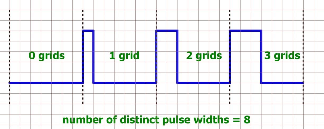
Let’s assume that the PWM signal shown in the diagram is restricted to pulse widths that are a multiple of one grid. This means that the duty cycle can assume 8 distinct values: 0%, ~14%, ~29%, ~43%, ~57%, ~71%, ~86%, and 100%. Each duty cycle corresponds to a particular output voltage, so what we have here is a 3-bit DAC, because 23 = 8.
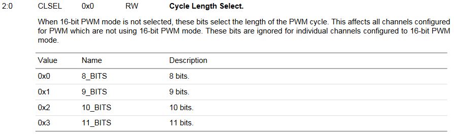
To determine the resolution of your real-life PWM DAC, just apply this same analysis: how many distinct duty cycles can you generate? It is usually not too difficult to answer this question, because the central element in a standard PWM hardware block is an N-bit counter that controls the width of the pulse, meaning that the equivalent DAC resolution is 2N. For example, the datasheet for Atmel’s SAM4S microcontroller series includes the following characteristics for its PWM controller:
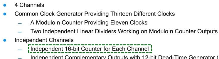
That 16-bit counter means 16 bits of resolution, or 216 = 65,536 distinct voltages ranging from 0 V to VDDIO (which can be anywhere from 1.62 V to 3.6 V). As another example, Silicon Labs’ EFM8UB1 microcontrollers feature variable PWM resolution, and consequently the reference manual is explicit regarding the resolution specs:

Conclusion
At this point, it may seem like there is hardly any use for a regular DAC when you can get 16 bits of resolution from a PWM-plus-RC-filter implementation. But of course, this is not the whole story—there is more to a DAC than resolution. In the next article, we will use simulations to more thoroughly explore concepts, circuits, and performance limitations related to PWM digital-to-analog conversion.
Next Article in Series: Low-Pass Filter a PWM Signal into an Analog Voltage


Very cool stuff, pretty new to the site, but this was definitely a great/interesting read.
Thank you for a cool article. In trying to protect my Arduino using a cascode configuration for a base transistor signal, initially with a high frequency PWM (e.g. pin 5 can run at 64KHz) , I stumbled upon an option that works at low frequency, even below 20 Hz!
The normal cascode arrangement has the top transistor base gounded, that forms a current follower. I realized that what was needed was a voltage follower on the top, using two NPNs in series with a Q resistor in between. Connecting the top NPN base to collector using a 220 Ohm resistor, and a voltage divider of VCC or voltage regulator and applying the PWM signal to the base of the bottom NPN (voltage clamped with a signal diode and resister in series), one can flatten out the signal to the top NPN collector and produce a DAC. I used a generic 5 Volt regulator, and lowered the input voltage to the top NPN collector to 1.2 Volts, and got a 20mV resolution flat and clean DAC from the top NPN collector by applying the PWM to the base of the bottom NPN. Works like a charm and one can put capacitors etc… to ground off the top collector to ground to further flatten I suppose.