 Facebook
 Google
 GitHub
 Linkedin
Real Time Clocks (RTCs) in Microcontroller Timers
This article is the third of a series on microcontroller timers which describes the RTCs inside a microcontroller.
This article is the third of a series on microcontroller timers. The first article describes the major features of most types of timers and covers periodic timers, and the second covers pulse width modulation MCU timers.
Real-time clocks (RTC) are timers dedicated to maintaining a one-second timebase. In addition, an RTC is often used to keep track of clock time and calendar date either in software or hardware. Many of the features of an RTC are very specialized and required for maintaining high accuracy and very reliable operation. There are RTC devices external to a microcontroller which interface with an I2C or SPI bus.
This article describes RTCs inside a microcontroller.
Overview of Real-time Clocks
The real-time clock's basic function is to produce intervals of one second and maintain a continuous count.
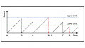
You can see a representation of this in the diagram below.

Figure 1. This timing diagram depicts the basic function of an RTC
Also shown is a program function, A, reading a seconds counter and scheduling an event, B, to occur three seconds in the future. This action is called an alarm. Notice the seconds counter runs continuously and does not stop and start. Two primary requirements of an RTC are accuracy and continuous operation.
The next diagram shows common hardware features of an RTC.
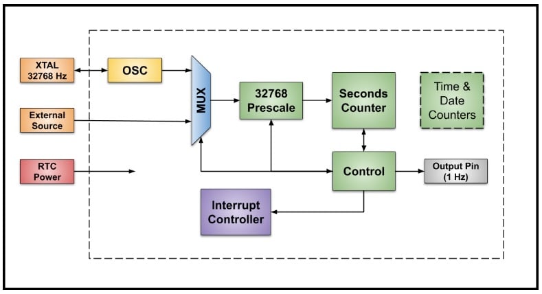
Figure 2. Real-time clock hardware features
An RTC often has its own internal oscillator with an external crystal and an option to use an external frequency reference. All clock sources run at 32,768 Hz. An external clock source allows the use of a very accurate and stable device such as a TCXO (temperature-compensated crystal oscillator).
A clock source is selected with a multiplexer and input to a prescaler which divides the clock by a factor of 32,768 (215) to produce a one-second clock.
A basic RTC has a seconds counter which is usually 32 bits or more. Some RTCs have specialized counters to keep track of the time of day and the calendar date.
A basic RTC without time and date counters uses software for this purpose. A common option is a 1 Hz square wave from an output pin. An RTC will have several possible events to generate a processor interrupt.
An RTC often has a dedicated power pin to allow operation when the rest of the microcontroller is powered down. This power pin is typically connected to a battery or separate power supply.
RTC Accuracy and Frequency Compensation
The accuracy of an RTC depends on the 32,768 Hz clock source. In a well-designed crystal oscillator, the major source of error is the crystal. An external TCXO can be used for highly accurate timing, or special frequency compensation techniques are used with less expensive crystals and the internal oscillator. There are three major sources of error from a crystal.
- Initial circuit and crystal tolerance
- Crystal drift with temperature
- Crystal aging
The graph below shows several concepts related to RTC accuracy.

Figure 3. Graph showing error measurement using temperature used courtesy of Texas Instruments
The dark blue trace on this graph shows a typical initial tolerance and the change with temperature. The pink trace shows just the temperature error. The key to compensating for temperature is the fact that the behavior of a crystal is well known and predicted with a quadratic equation. If the initial error is measured after the circuit board is manufactured and the temperature is known, it is possible to compensate for the largest error sources.
The yellow band is a reasonable target for accuracy after careful compensation. Keep in mind 1 ppm over a year is about 30 seconds. Crystal aging is difficult to compensate for. Fortunately, aging is usually only a few ppm per year.
How to Change RTC Timing
Here are two ways to change the timing of an RTC as part of a system to compensate for errors.
The first diagram (Figure 4) depicts the number of oscillator cycles counted by the prescaler for each period of the seconds counter.
The first two seconds are the usual 32,768 cycles. The software uses temperature readings and the initial error to determine that the oscillator is running a little fast and 32,768 cycles is actually a period of 0.99990 seconds. To compensate for this small error, the software tells the RTC to change the modulus of the prescaler to 32,781 for every fourth second to add some time.

Figure 4. A representation of oscillator cycles counted by a prescaler
This technique has the advantage of a small change in the period from second to second. However, the technique requires an adjustable prescaler and additional registers to hold the special prescale count and the number of seconds between application of the special count. I think this is pretty cool. A little complicated but pretty cool.
What if the RTC does not have a special prescaler to adjust the timing? This diagram shows another method.

Figure 5. The same situation as shown in Figure 4, but without a prescaler
In this case, the number in the boxes is the seconds counter. The count shown is 100251 followed by 100252. The software has been continuously calculating the adjustment and keeping track of the RTC seconds count. When the error accumulates to exactly one second, the software adds or subtracts a second to adjust for the accumulated error.
A disadvantage of this technique is the change from second to second is large when an adjustment is done. This technique has the advantage of compatibility with any RTC.
Security in RTCs
Security is an interesting requirement. There are applications where time is used for billing customers for using a service or consuming a resource. There is an extensive body of practice around preventing or detecting hacks of RTCs. Techniques range from intrusion detection for enclosures to special features within the microcontroller.
The RTC on a microcontroller that I am currently using has special registers to allow software to permanently lock critical registers. Once locked, they cannot be changed and are protected from hacking or out-of-control code. Changing the time requires a complete reset of the microcontroller.
Time and Date
Some RTCs have hardware counters to maintain the time of day and calendar date. This requires counters for minutes, hours, days, months, years, and consideration for leap years. Time of day and calendar dates can also be kept by software.
A prominent example would be the functions in the C Standard Library seen in the time.h file. For a microcontroller, this system can be based on the seconds counter of an RTC. Four small, custom functions must be written to fully support the time.h library.
The one function of interest here is called by the time( ) function in the library, which returns the time as the number of seconds since a starting point called an “epoch,” usually January 1, 1970. Typically, the custom function to read the hardware timer is named get_time( ) or a similar variation. All get_time( ) does is read the seconds counter and return the value. The library does the rest to turn this time in seconds to the current time of day and date.
Issues with 32-Bit Second Counters
A 32-bit second counter runs for a long time but not forever. There can be serious issues because of the limited count range. For example, a system time based on a 32-bit counter using the C standard library and an epoch of January 1, 1970, could fail in January of 2038 when the counter rolls over after the maximum count. This issue is known as the Y2038 problem.
A failure occurred during the NASA Deep Impact space mission to study a comet. The primary mission goal was achieved and the spacecraft continued on to study other objects. However, communication was suddenly lost in 2013. Here is an official NASA comment.
“Although the exact cause of the loss is not known, analysis has uncovered a potential problem with computer time tagging that could have led to loss of control for Deep Impact's orientation.”
A likely cause of failure is that a 32-bit timer was maintaining the time in increments of 0.1 seconds and rolled over causing “termination” of the mission.
My suggestion, when time and date are involved, is to use a longer than expected lifetime in your design.
What’s Next
The next article concludes the series with Watchdog timers.
Related Content


Hi Stephen,
Very good article to get first hand insight into RTC. Thank you.
Yet couple of questions still bother me…
1) The main application of RTC is get information about current time or to get exact time of a past event or to perform an event in a time synchronisation manner. Which means, a specific event taking place at a specific point of time (e.g. 24.April 2021, 08hrs 15min 31sec with reference to GMT 00:00:00) is represented as differently local time in Newyork(04h:15m:31s) or in Berlin(10h:15::31s) or in Bangalore (13h:45m:31s). So an embedded device using RTC(e.g. Microwave oven) in Newyork, other such devices in Berlin or in Bangalore, they should all have a common reference synchronised time reference. But the RTC clock is internally generated in each of embedded device separately. How do each of the device get synchronised to each other, when each device is working independent of other devices and all devices are not connected to network?
2) When they are not synchronised to a common reference master, even though each device may have a clock source and a timer to calculate time, can this be called as RTC in the real sence?
3) Is there really anything like ‘master RTC’ running somewhere in the world, which can be taken as reference for time synchronisation?