Facebook
 Google
 GitHub
 Linkedin
DC Lab - Current Divider
Project Overview
In this project, you will build a current divider circuit using resistors and measure the currents using an ammeter. We will demonstrate how you can build the current divider circuit using three different methods:
- On a breadboard (as shown in Figure 1)
- On a terminal strip
- Free-form using alligator-style clips
This will familiarize you with the different circuit-building techniques and their relative advantages and disadvantages.
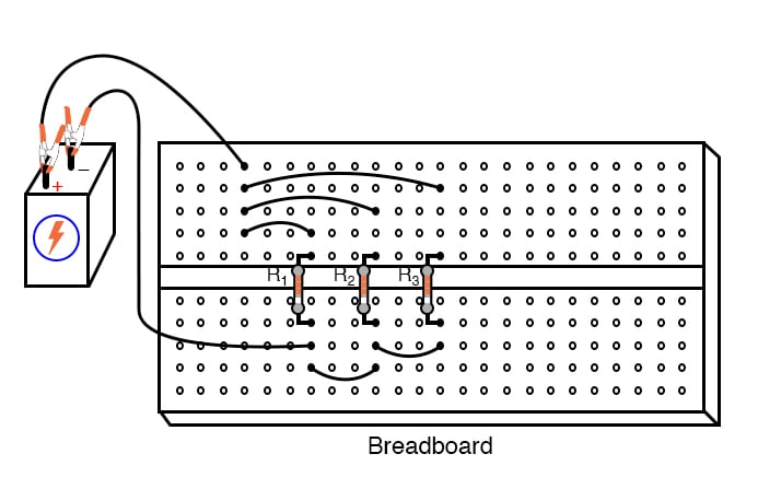
Figure 1. Breadboard implementation of a resistive current divider circuit.
Parts and Materials
- 6 V battery
- Assortment of resistors between 1 kΩ and 100 kΩ in value
Learning Objectives
- Voltmeter use
- Ammeter use
- Ohmmeter use
- Application of Ohm’s Law
- Application of Kirchhoff’s current law (KCL)
- Current divider design
Instructions
Step 1: Select three resistors from your resistor assortment and measure the resistance of each one with an ohmmeter. Record these resistance values for reference in your circuit calculations.
Step 2: Next, connect the three resistors in parallel with the 6 V battery, as shown in the circuit schematic of Figure 2.
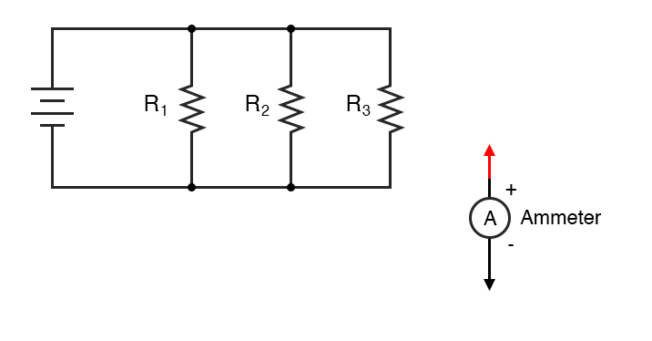
Figure 2. Schematic diagram of a current divider circuit built with resistors.
Build the Current Divider Circuits
We will demonstrate three different construction techniques for building a current divider:
- Breadboard
- Terminal strip
- Free-form
Each of these construction methods can be used to build the circuit in Figure 2.
The breadboard construction of the current divider, as illustrated in Figure 3, is easy to build for compact, temporary circuits.
Figure 3. Breadboard implementation of a resistive current divider circuit.
Figure 4 shows the current divider built using terminal strips to provide a more permanent construction than the breadboard.
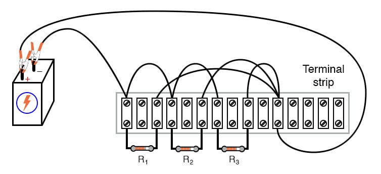
Figure 4. Terminal strip implementation of a resistive current divider circuit.
Normally, it is considered improper to secure more than two wires under a single terminal strip screw. In this illustration, you can see three wires joining at the top screw of the rightmost lug used on this strip. This is done for the ease of proving a concept (of current summing at a circuit node) and does not represent a professional assembly technique.
On the other hand, the free-form circuit construction method uses alligator-style clips and jumper wires. Figure 5 shows a free-form design of a resistive current divider.
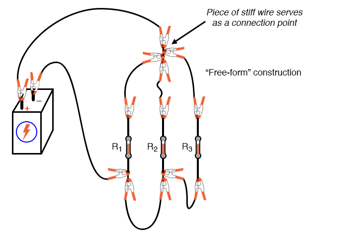
Figure 5. Free-form implementation of a resistive current divider circuit.
The non-professional nature of the free-form construction method merits no further comment.
Measure the Circuit Voltages
Step 3: Measure the battery voltage with a voltmeter and record the value. It may differ slightly from a no-load condition. The battery voltage may be reduced under load due to the internal series resistance of the battery. However, using resistance values greater than 1 kΩ ensures that this three-resistor circuit should not draw enough current to cause a significant voltage drop. Keep in mind, however, measuring the battery voltage under load is good practice.
Step 4: Measure the voltage across each of the three resistors. What do you notice? In a parallel circuit like this current divider, voltage is the common variable between all components.
Calculate and Measure the Currents
Step 5: Use Ohm’s law to calculate the expected current through each resistor, Rn where n = 1, 2, or 3.
$$I_n = \frac{V_{battery}}{R_n}$$
Step 6: Now, verify these calculated values by measuring the currents with a digital ammeter. You can do this by placing the red probe of the ammeter at the point where the positive (+) ends of the resistors connect to each other. From there, you can lift one resistor wire at a time, connecting the meter’s black probe to the lifted wire, as shown in Figure 6 for the breadboard and Figure 7 for the terminal strip. In these illustrations, you can see an ammeter is used to measure the current through R1.
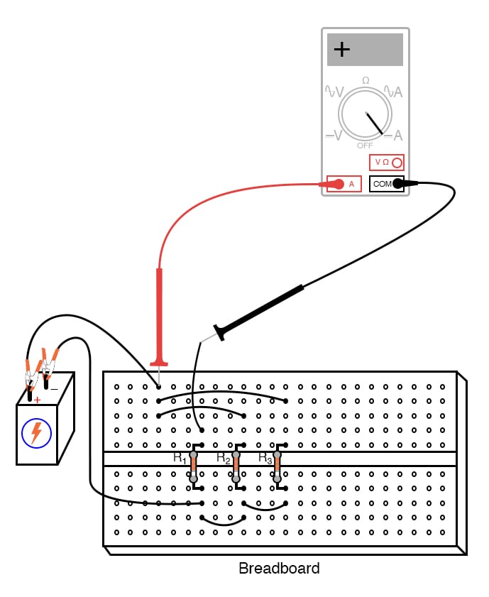
Figure 6. Using an ammeter to measure the current through the R1 branch of the breadboard resistive divider circuit.
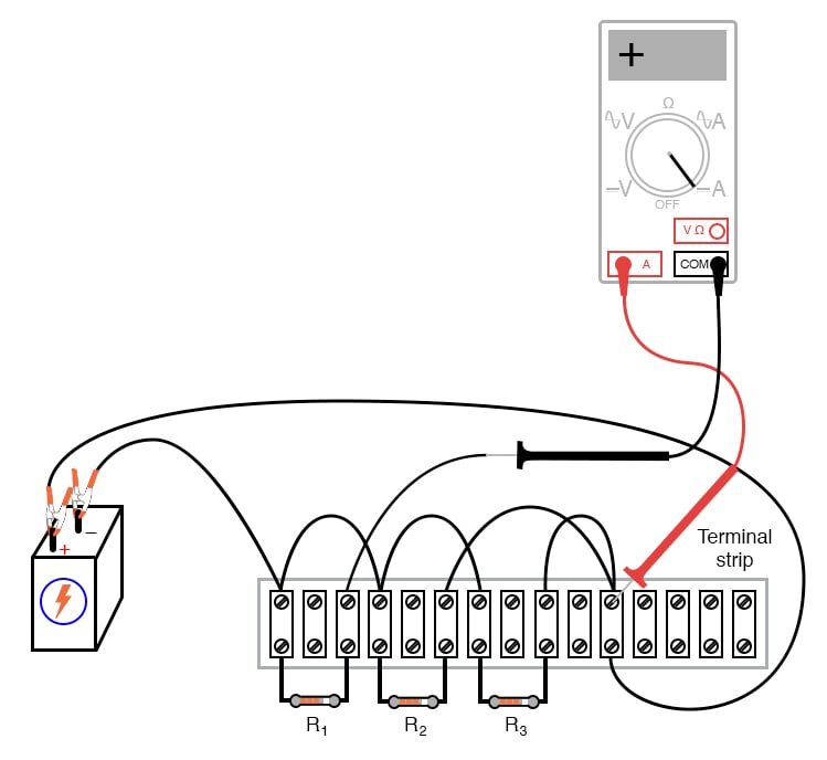
Figure 7. Using an ammeter to measure the current of the R1 branch of the terminal-strip resistive divider circuit.
Afterward, you can repeat this technique to measure each resistor current, noting both the magnitude of the current and the polarity. With the digital ammeter connected as shown, all three current measurements should be positive, not negative.
Step 7: Next, measure the total circuit current as illustrated in Figures 8 and 9 for the breadboard and terminal-strip circuits, respectively.
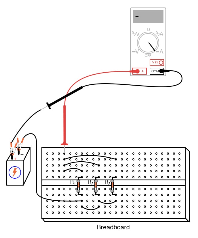
Figure 8 Using an ammeter to measure the total current of the breadboard resistive divider circuit.
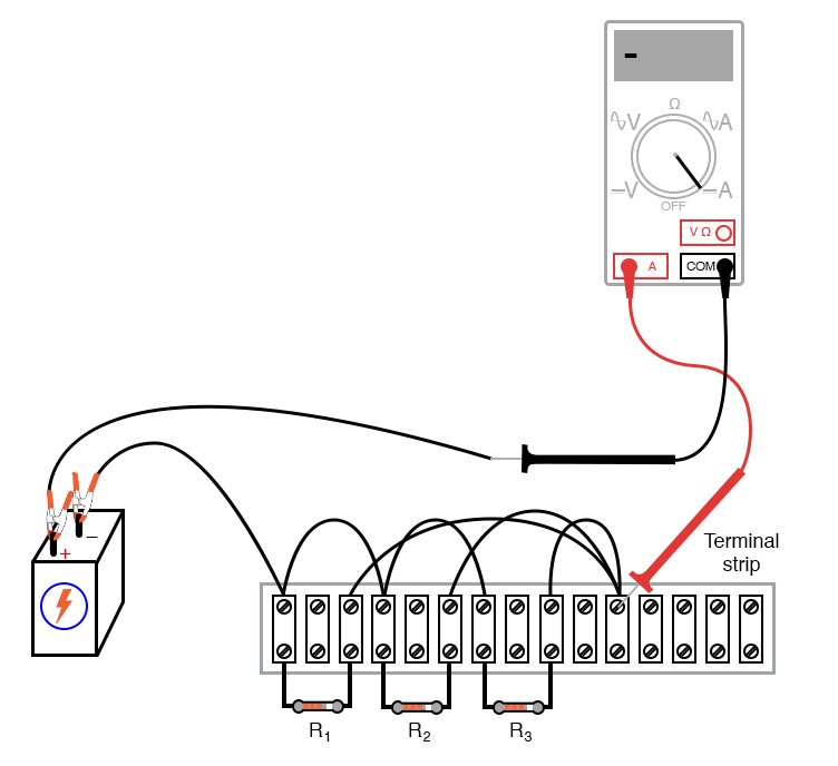
Figure 9. Using an ammeter to measure the total current of the terminal-strip resistive divider circuit.
Keep the ammeter’s red probe on the same point of the circuit, but disconnect the wire leading to the positive (+) side of the battery and touch the black probe to it. Be sure to note both the magnitude and the sign of the current as indicated by the ammeter.
Kirchhoff’s Current Law (KCL) Experimental Validation
Step 8: The next part of this experiment is validating Kirchhoff’s current law. First, add the total current figure (algebraically, including signs) to the three individual resistor currents.
$$I_{total} + I_1 + I_2 + I_3 = 0$$
What do you notice about the result that is similar to Kirchhoff’s voltage law experiment using a voltage divider? Kirchhoff’s current law is to currents “summing” at a point (node) in a circuit, just as Kirchhoff’s voltage law is to voltages adding in a series loop: in both cases, the algebraic sum is equal to zero.
This law is also useful in the mathematical analysis of circuits. Along with KVL, KCL allows us to generate equations describing several variables in a circuit, which may then be solved using various mathematical techniques.
Step 9: Now consider the four current measurements as all positive numbers: the first three representing the current through each resistor, and the fourth representing the total circuit current as a positive sum of the three branch currents. Each resistor (branch) current is a fraction, or percentage, of the total current. This is why a parallel resistor circuit is often called a current divider.
Ohm's Law Validation for Parallel Resistors
Step 10: Disconnect the battery from the rest of the circuit, and measure the resistance across the parallel resistors. You may read total resistance across any of the individual resistors’ terminals and obtain the same result. It will be a value less than any of the individual resistor values.
$$R_{total} = \frac{1}{\frac{1}{R_1} + \frac{1}{R_2} + \frac{1}{R_3}}$$
This is often surprising to new students of electricity that you read the exact same (total) resistance figure when connecting an ohmmeter across any one of a set of parallel-connected resistors. It makes sense, though, if you consider the points in a parallel circuit in terms of electrical commonality. All parallel components are connected between two sets of electrically common points.
Since the meter cannot distinguish between points common to each other by way of direct connection, to read the resistance across one resistor is to read the resistance of them all. The same is true for voltage, which is why battery voltage could be read across any one of the resistors as easily as it could be read across the battery terminals directly.
Step 11: Calculate the total current by dividing the battery voltage (previously measured) by the total resistance figure you measured:
$$I_{total} = \frac{V_{battery}}{R_{total}}$$
You should obtain a calculated figure for the total current that closely matches the measured figure.
The ratio of resistor current to total current is the same as the ratio of total resistance to individual resistance. For example, if a 10 kΩ resistor is part of a current divider circuit with a total resistance of 1 kΩ, that resistor will conduct 1/10 of the total current, whatever value that current total happens to be.
SPICE Simulation of a Resistive Current Divider Circuit
Figure 10 shows how to define the current divider circuit for computer simulation.
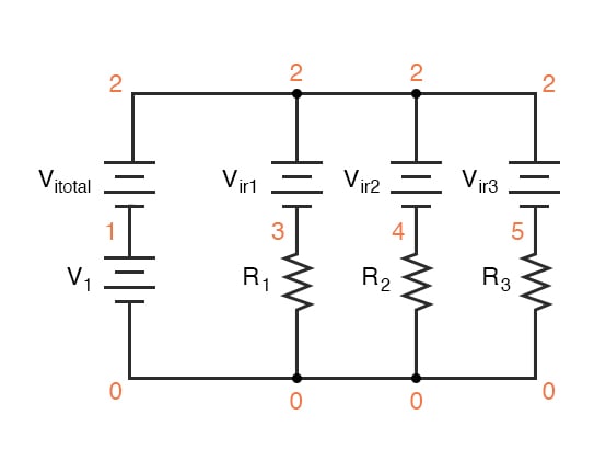
Figure 10 Adding node numbers and power supplies for SPICE simulation of the resistive divider circuit.
Ammeters in SPICE simulations are actually zero-voltage sources inserted in the paths of current flow. You will notice the voltage sources Vir1, Vir2, and Vir3 are set to 0 V in the netlist below. When currents enter the positive side of one of these “dummy” voltage sources and out the negative side, the battery’s current indication will be a positive number. In other words, these 0-volt sources are to be regarded as ammeters with the red probe on the long-line side of the battery symbol and the black probe on the short-line side.
Step 12: Make a text file containing the following netlist, verbatim:
Current divider
v1 1 0
r1 3 0 2k
r2 4 0 3k
r3 5 0 5k
vitotal 2 1 dc 0
vir1 2 3 dc 0
vir2 2 4 dc 0
vir3 2 5 dc 0
.dc v1 6 6 1
.print dc i(vitotal) i(vir1) i(vir2) i(vir3)
.end
When run, SPICE will print a line of text containing four current figures. The first current represents the total as a negative quantity, and the other three represent currents for resistors R1, R2, and R3. When algebraically added, the one negative figure and the three positive figures will form a sum of zero, as described by Kirchhoff’s current law.
Related Content
Learn more about the fundamentals behind this project in the resources below.
Calculators
Worksheets
Textbook