 Facebook
 Google
 GitHub
 Linkedin
Branch Current Method Analysis
What is the Branch Current Method Used in Network Analysis?
The branch current method is a network analysis technique in which branch current directions are assigned arbitrarily, and then Ohm’s law and Kirchhoff’s current and voltage laws are applied systematically to solve for the unknown currents and voltages.
The most straightforward DC network analysis technique is the branch current method. In this method, we assume the directions of the currents in the circuit and then write equations describing their relationships to each other through Kirchhoff’s current law (KCL), Kirchhoff’s voltage law (KVL), and Ohm’s law. Once we have one equation for every unknown current, we can solve the simultaneous equations and determine all currents and, therefore, all voltage drops in the network.
Selecting a Circuit Node and Branch Current Assignments
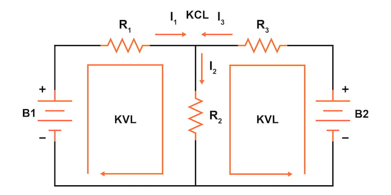
To begin with, let’s use the circuit in Figure 1 to explain the application of the branch current method. We will use this same example circuit to teach other network analysis methods, including Mesh Current, Superposition Theorem, Thevenin’s Theorem, Norton’s Theorem, and Millman’s Theorem.
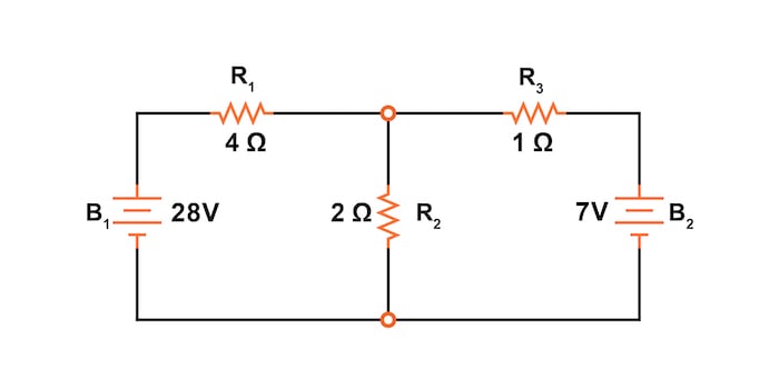
Figure 1. Circuit for explaining the branch current method.
Select a Circuit Node
The first step is to choose a node (junction of wires) in the circuit to use as a point of reference for our unknown currents. We’ll choose the node joining the right of R1, the top of R2, and the left of R3, as shown in Figure 2.

Figure 2. Select a circuit node at which you will define the unknown currents.
Assign Currents at the Node
At this node, we will guess which directions the three wire’s currents take, labeling the three currents as I1, I2, and I3, respectively, as illustrated in Figure 3.
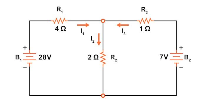
Figure 3. Define all the unknown currents at the selected node.
Keep in mind that these directions of current are speculative at this point. Fortunately, if it turns out that any of our guesses were wrong, we will know when we mathematically solve for the currents—any “wrong” current directions will show up as negative numbers in our solution.
Apply Kirchhoff’s Current Law at the Selected Node
Kirchhoff’s current law tells us that the algebraic sum of currents entering and exiting a node must equal zero. Thus, we can relate these three currents (I1, I2, and I3) to each other in a single equation.
For the sake of convention, let’s denote any current entering the node as a positive and any current exiting the node as negative. This situation gives us the following KCL equation:
$$I_1 - I_2 + I_3 = 0$$
Apply Kirchhoff’s Voltage Law Around the Circuit Loops
Next, we’ll use KVL around the loops in the circuit to develop a set of equations that will allow us to solve for unknown equations.
Step 1: Label All Voltage Drops
Before applying KVL, we will label all of the voltage drop polarities across resistors according to the assumed directions of the currents. The polarity is positive where the current enters the resistor and negative where it exits the resistor, as shown in Figure 4.
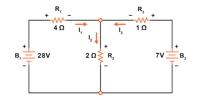
Figure 4. Label the voltage drops across the resistors.
The polarity or the resistor voltages is consistent with a load that is dropping voltage. The voltage will be higher on the side the current enters the resistor and lower where it exits.
The battery polarities remain as they were according to their symbology, with the short-end negative and the long-end positive. Since batteries are sources, the voltage is higher on the side the current exits—just the opposite of the resistive loads.
Keep in mind that it is okay if the polarity of a resistor’s voltage drop doesn’t match with the polarity of the nearest battery, so long as the resistor voltage polarity is correctly based on the assumed direction of the current through it. In some cases, we may discover that current will be forced back through a battery, causing this effect (an example of reverse current flow into a battery is when charging a rechargeable battery).
The important thing to remember here is to base all your resistor polarities and subsequent calculations on the directions of currents initially assumed. As stated earlier, if your assumption happens to be incorrect, it will be apparent once the equations have been solved. A negative current and resistance simply mean the current flows opposite to the direction of our initial guess. The magnitude of the solution, however, will still be correct.
Step 2: Apply Kirchhoff’s Voltage Law (KVL) to the Left Circuit Loop
Kirchhoff’s voltage law tells us that the algebraic sum of all voltages in a loop must equal zero. We must tally voltage drops in a loop of the circuit as though we measure with a real voltmeter.
First, let’s trace the left loop of this circuit first, starting from the upper-left corner and moving counter-clockwise (the choice of starting points and directions is arbitrary). The sequence of voltage measurements is shown below in Figures 5 through 8.

Figure 5. Measure the voltage across battery B1.
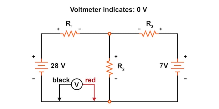
Figure 6. Measure the voltage across the bottom wire segment.
_.jpg)
Figure 7. Measure the voltage across resistor R2.
_.jpg)
Figure 8. Measure the voltage across resistor R1.
Having completed our trace of the left loop, we can add these voltages together with a sum of zero as required by KVL:
$$-28 + 0 + V_{R2} + V_{R1} = 0$$
Next, we can eliminate the zero voltage term on the left to simplify this equation:
$$-28 + V_{R2} + V_{R1} = 0$$
As an aside, it should be relatively easy to see that we could have skipped measuring that 0 V section of the loop since it is a single electrical node. This node, by definition, cannot have a voltage drop. However, we left it in our development of the branch current method for consistency.
From here, we don’t yet know the voltages across R1 or R2, so we can’t insert those values into the equation as numerical figures at this point. However, we do know that all three voltages must algebraically add to zero, thus, the equation is true.
Step 3: Express the Voltages in Terms of the Unknown Currents
Going a step further, we can now express the unknown voltages as the product of the corresponding unknown currents (I1 and I2) and their respective resistors by following Ohm’s law (V = IR):
$$-28 + I_2R_2 + I_1R_1 = 0$$
Since we know what the values of all the resistors are in ohms, we can just substitute those figures into the equation to simplify things a bit:
$$-28 + 2I_2 + 4I_1 = 0$$
You might wonder why we went through all the trouble of manipulating this equation from its initial form (-28 + VR2 + VR1). After all, the last two terms are still unknown, so what advantage is there to expressing them in terms of unknown voltages or as unknown currents (multiplied by resistances)?
Basically, this gets the KVL equation expressed using the same unknown variables as our original KCL equation. To solve for three unknown currents (I1, I2, and I3), we must have three equations relating these three currents (not voltages!) together. This will allow us to use algebraic methods for solving simultaneous equations.
Step 4: Apply Kirchhoff’s Voltage Law (KVL) to the Right Circuit Loop
Next, let’s apply the same steps to the right loop of the circuit, beginning by recording the voltage drops. We’ll arbitrarily start at the originally chosen node and move counter-clockwise around the right loop, as illustrated in Figures 9 through 12.
_.jpg)
Figure 9. Measure the voltage across resistor R2.

Figure 10. Measure the voltage across the bottom wire segment.

Figure 11. Measure the voltage across battery B2.
_.jpg)
Figure 12. Measure the voltage across resistor R3.
After that, let’s write out the KVL equation for the voltages around the right loop:
$$-V_{R2} + 0 + 7 - V_{R3} = 0$$
Knowing now that the voltage across each resistor should be expressed as the product of the corresponding current and the (known) resistance of each resistor, we can rewrite the equation as:
$$-I_2R_2 + 7 - I_3R_3 = 0$$
Again, note that we have again dropped the 0 V term.
Now, let’s insert the resistance values in ohms:
$$-2I_2 + 7 - 1I_3 = 0$$
Solve the Simultaneous Equations for the Unknown Currents
At this point in the process, we have a mathematical system of three equations (one KCL equation and two KVL equations) and three unknowns:
$$I_1 - I_2 + I_3 = 0 \text{ (Kirchhoff’s Current Law)}$$
$$-28 + 2I_2 + 4I_1 = 0 \text{ (Kirchhoff’s Voltage Law)}$$
$$2I_2 + 7 - 1I_3 = 0 \text{ (Kirchhoff’s Voltage Law)}$$
For some solution methods (especially any method involving a calculator or computer), it is often helpful to express the equations following two simple rules:
- Include a coefficient in front of each unknown term, even if the coefficient is 0 or 1
- Move all constant values to the right of the equal sign
Rewriting the equations following these guidelines we have:
$$1I_1 - 1I_2 + 1I_3 = 0 \text{ (Kirchhoff’s Current Law)}$$
$$4I_1 + 2I_2 + 0I_3 = 28 \text{ (Kirchhoff’s Voltage Law)}$$
$$0I_1 + 2I_2 +1I_3 = 7 \text{ (Kirchhoff’s Voltage Law)}$$
Using whatever techniques are available to you for solving simultaneous equations, you should arrive at the following solutions for the three unknown current values:
$$I_1 = 5 \text{ A}$$
$$I_2 = 4 \text{ A}$$
$$I_3 = -1 \text{ A}$$
Thus:
- I1 is 5 A
- I2 is 4 A
- I3 is a negative 1 A
However, what does “negative” current mean? In this case, it means that our assumed direction for I3 (into the chosen node) was the opposite of its real direction.
Redraw the Circuit
Going back to our original circuit, we can redraw the current arrow for I3 in the correct direction and redraw the polarity of the voltage drop across R3 to match, as shown in Figure 13.

Figure 13. Solution of our circuit currents and voltage drops.
Notice how current is being pushed backward through the second battery (B2) due to the higher voltage of the first battery (B1). Even though battery B2‘s polarity is trying to push current towards resistor R3 in that branch of the circuit, the current is actually being forced back through it due to the superior voltage of battery B1.
Does this mean that the stronger battery will always “win” and the weaker battery will always have current forced through it backward? No!
It actually depends on both the batteries’ relative voltages and the resistor values in the circuit. The only sure way to determine what’s going on is to take the time to mathematically analyze the network.
Calculate the Voltage Drop Across All Resistors
Now that we know the magnitude of all currents in this circuit, we can calculate the voltage drops across all resistors with Ohm’s law (V = IR):
$$V_{R1} = I_1R_1 = \text{(5 A)(4 }\Omega) = 20 \text{ V}$$
$$V_{R2} = I_2R_2 = \text{(4 A)(2 }\Omega) = 8 \text{ V}$$
$$V_{R3} = I_3R_3 = \text{(1 A)(1 }\Omega) = 1 \text{ V}$$
Network Analysis Using SPICE
Finally, let us now analyze this same network of Figure 13 using SPICE to verify our voltage results. As a side note, we could also analyze current with SPICE, which requires inserting extra voltage sources into the circuit. Besides, we know that if the voltages are all the same and the resistances are the same, the currents must all be the same. In that case, we will opt for the less complex analysis.
Figure 14 is a re-drawing of our circuit, complete with node numbers for SPICE to reference.
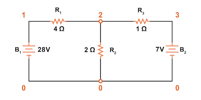
Figure 14. Adding SPICE node numbers to the circuit.
Branch Current Network Analysis Example

v1 1 0

v2 3 0 dc 7

r1 1 2 4

r2 2 0 2

r3 2 3 1

.dc v1 28 28 1 .print dc v(1,2) v(2,0) v(2,3)

.end

v1         v(1,2)     v(2)       v(2,3)

2.800E+01  2.000E+01  8.000E+00  1.000E+00
Sure enough, the voltage figures all turn out to be the same:
- 20 V across R1—nodes 1 and 2, v(1,2)
- 8 V across R2—nodes 2 and 0 with 0 implied in v(2)
- 1 V across R3—nodes 2 and 3, v(2,3)
Take note of the signs of all these voltage figures; they’re all positive values. SPICE bases its polarities on the order that the nodes are listed. The first node is positive, and the second node is negative.
For example, a result of positive +20 V between nodes 1 and 2 means that node 1 is positive concerning node 2. If the figure had come out negative in the SPICE analysis, we would have known that our actual polarity was backward (node 1 is negative concerning node 2).
Checking the node orders in the SPICE listing, we can see that the polarities all match what we determined through our branch current method of analysis.
Branch Current Method Review
- Choose a node and assume directions for all currents at the node
- Write a KCL equation relating currents at the chosen node
- Label resistor voltage drop polarities based on assumed current directions
- Write KVL equations for each loop of the circuit, substituting the product IxRx for Vx in each resistor term of the equations
- Solve for unknown branch currents using simultaneous equations
- If any current solution is negative, then the assumed direction of current for that solution is wrong
- Solve for the voltage drops across all resistors (V = IR)
Related Content
Below you’ll find additional resources to learn more about the branch current analysis:
Calculators:
Worksheets:
- DC Branch Current Analysis Worksheet
- Kirchhoff's Laws Worksheet
- Voltage, Current, and Resistance Worksheet
Video Tutorials and Lectures:
Technical Articles:
- Resistors in Parallel: Circuit Analysis with Parallel Resistance
- Special Cases in Nodal Analysis
- Nodal Analysis and Dependent Sources


How do you get from
−28+I2R2+I1R1=0
to
−28+2I2+4I1=0
it seems wrong, you have to consider the both current flow for R2 (2ohm) in each loop, so the current should be I2+I3 for R2?