 Facebook
 Google
 GitHub
 Linkedin
Converting Between Thevenin and Norton Equivalent Circuits
Learn to Convert Between Thevenin and Norton's Equivalent Circuits
This article provides a simple explanation of how to convert between Thevenin and Norton equivalent circuits.
Since Thevenin’s theorem and Norton’s theorems are two equally valid methods of reducing a complex network down to something simpler to analyze, there must be some way to convert a Thevenin equivalent circuit to a Norton equivalent circuit and vice versa. Thankfully, the procedure is fairly simple.
Thevenin and Norton's equivalent circuits are intended to behave the same as the original network in supplying voltage and current to the load resistor (as seen from the perspective of the load connection points). Therefore, these two equivalent circuits should behave identically. We will use this principle to derive our conversions between the two equivalent circuits.
The Thevenin Resistance is Equal to the Norton Resistance
The procedure for calculating the Thevenin equivalent resistance is identical to that for calculating the Norton equivalent resistance. Below are the three main steps:
- Step 1: Remove the Load Resistor
- Step 2: Replace the Power Sources
- Step 3: Calculate the Nortan Resistance
Since the procedures are identical, the Thevenin and Norton resistances for any circuit must be equal. Figure 1 is the example circuit we used when explaining how to calculate the equivalent circuits.
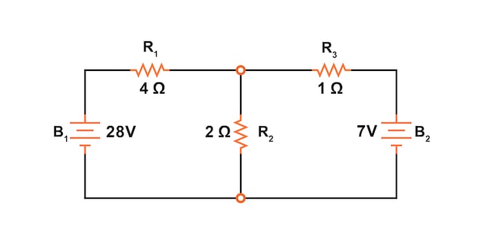
Figure 1. Circuit schematic for explaining Thevenin’s and Norton’s theorems.
Figures 2 and 3 are the Thevenin and Norton equivalent circuits, respectively, for the circuit of Figure 1.

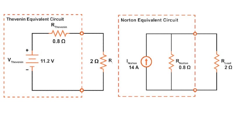
Figure 2. Thevenin equivalent circuit.
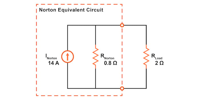
Figure 3. Norton equivalent circuit.
As shown, the Thevenin and Norton resistances are identical, 0.8 Ω. Therefore, we can conclude that the Norton and Thevenin resistances are equivalent:
$$R_{Thevenin} = R_{Norton}$$
Converting a Norton Current Source to a Thevenin Voltage Source
Thevenin and Norton equivalent circuits should produce the same voltage across the load terminals with no load resistor attached. For the Thevenin equivalent, the open-circuited voltage would equal the Thevenin source voltage, which is 11.2 V in our example.
With the Norton equivalent circuit and no load resistor, all 14 A from the Norton current source would have to flow through the 0.8 Ω Norton resistance. The voltage at the load terminals would then also be 11.2 V:
$$V = I \cdot R = (14 \text{ A})\cdot (0.8 \text{ }\Omega) = 11.2 \text{ V}$$
Thus, we can conclude that the Thevenin voltage is equal to the Norton current multiplied by the Norton resistance:
$$V_{Thevenin} = I_{Norton} \cdot R_{Norton}$$
Thus, if we wanted to convert a Norton equivalent circuit to a Thevenin equivalent circuit, we could use the same resistance and calculate the Thevenin voltage using Ohm’s law.
Converting a Thevenin Voltage Source to a Norton Current Source
Conversely, both Thevenin and Norton equivalent circuits should generate the same amount of current through a short circuit across the load terminals. With the Norton equivalent, the short-circuit current would equal the Norton source current, which is 14 A for our example circuit.
With the Thevenin equivalent, all 11.2 V would be applied across the 0.8 Ω Thevenin resistance. The current through the circuit would then be given by:
$$I = \frac{V}{R} = \frac{11.2 \text{ V}}{0.8 \text{ }\Omega} = 14 \text{ A}$$
Thus, we can say that the Norton current is equal to the Thevenin voltage divided by the Thevenin resistance:
$$I_{Norton} = \frac{V_{Thevenin}}{R_{Thevenin}}$$
Review of Thevenin and Norton Conversions
- Thevenin resistance and Norton resistance are equal.
- Thevenin voltage is equal to the Norton current times the Norton resistance.
- Norton current is equal to the Thevenin voltage divided by the Thevenin resistance.
Related Content
Learn more about Thevenin's theorem, Norton's theorem, and circuit analysis in the additional resources down below.
Calculators:
Worksheets:
- Thevenin’s, Norton’s, and Maximum Power Transfer Theorems Worksheet
- Performance-Based Assessments for Network Analysis Competencies Worksheet
- Ohm's Law Worksheet
Video Tutorials and Lectures:
Technical Articles:
- Learn About Thevenin Theorem and Dependent Source Circuits
- Learning to Simplify: Thevenin and Norton Equivalent Circuits
- Analyzing Circuits via Source Transformation


The equality under the first drawing is incorrect. Both sides should be R subscript something.