 Facebook
 Google
 GitHub
 Linkedin
Superposition Theorem
How to Use the Superposition Theorem to Analyze a Linear Circuit?
The superposition theorem states that any linear circuit with more than one power source can be analyzed by summing the currents and voltages from each individual power source.
The superposition theorem is one of those strokes of genius that takes a complex subject and simplifies it (in this case, circuits) and breaks it down in a way that makes sense. While a theorem like Millman’s can also work well, it is not quite obvious why it works as well as it does. Superposition, however, is obvious, which we’ll dive into further.
In this article, we’ll go over the step-by-step process for applying the superposition theorem to easily analyze circuits with multiple voltages and/or current sources supplying power.
What is the Superposition Theorem?
The strategy used in the superposition theorem is to eliminate all but one source of power within a network at a time. Then, we use series and parallel circuit analysis techniques to determine voltage drops and currents within the modified network for each power source separately.
This process is then repeated sequentially by individually evaluating the circuit for every voltage and current source in the system. After each individual analysis has been completed, the voltage and current values are all “superimposed” on top of each other (added algebraically) to find the actual voltage drops and currents with all sources active.
Explaining the Superposition Theorem in Circuit Analysis
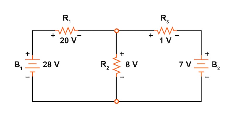
Before getting too far, let's explain the superposition theorem using the linear circuit example of Figure 1.
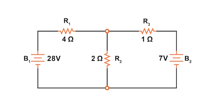
Figure 1. Circuit schematic for explaining the superposition theorem.
To make it easier to compare various network analysis methods, this is the same circuit we use to discuss:
Since we have two sources of power in this circuit, we will have to calculate two sets of values for voltage drops and/or currents—one set for the circuit with only the 28 V battery and a second set with only the 7 V battery.
Step 1: Replace All of the Power Sources Except for One
When replacing the power supplies in the circuits, we must follow these two rules:
- Replace all voltage sources with short circuits (wires)
- Replace all current sources with open circuits (breaks)
Since we only have voltage sources (batteries) in our example circuit in Figure 1, we will replace every inactive source during analysis with a short circuit wire. For example, in Figure 2, we have replaced the battery, B2, with a short circuit.
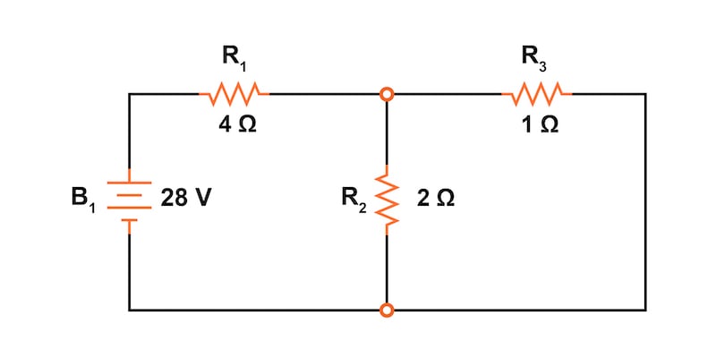
Figure 2. Battery B2 replaced with a short circuit
On the other hand, Figure 3 has a battery, B1, that has been replaced with a short circuit.
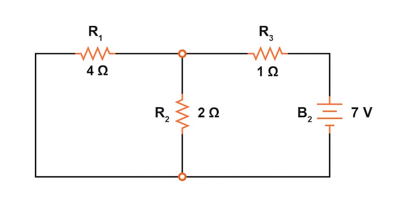
Figure 3. Battery B1 was replaced with a short circuit.
Step 2: Calculate the Voltages and Currents Due to Each Individual Source
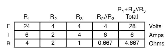
Analyzing the circuit of Figure 2 with only the 28 V battery using the table method, we obtain the values shown in Table 1 for each of the resistor voltage drops and resistor currents.
Table 1. Voltage and current values were calculated for the circuit with B2 removed.
Now, we can add the voltages and currents into the circuit drawing, as shown in Figure 4, paying careful attention to make sure we label the voltage drops with the correct polarity and the currents with the correct direction of flow.

Figure 4. Voltages and currents are added to the circuit powered only by battery B1.
This step will be critical when we begin superimposing values later.
Step 3: Repeat Steps 1 and 2 for Each Power Supply
Next, we’ll repeat this process for the circuit of Figure 3 with only the 7 V battery. The results are shown in Table 2 and Figure 5.
Table 2. Voltage and current values were calculated for the circuit with B1 removed.
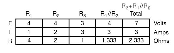

Figure 5. Voltages and currents are added to the circuit powered only by battery B2.
Step 4: Superimpose the Individual Voltages and Currents
When superimposing these values of voltage and current, we must be careful to consider the polarity of the voltage drop and the direction of the current flow, as the values have to be added algebraically.
Figure 6 shows the superposition of the resistor voltage drops.
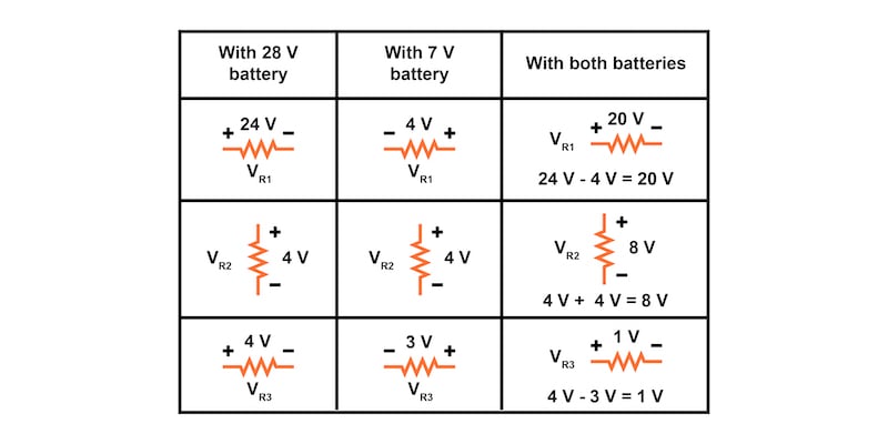
Figure 6. Superposition of the resistor voltage drops.
Meanwhile, Figure 7 shows the circuit after adding the superimposed voltage values.
Figure 7. Application of the superimposed voltage values.
The resistor currents add up algebraically as well and can either be superimposed using resistor voltage drops or calculated from the final voltage drops and respective resistances (I = V/R). Either way, the answers will be the same.
Figure 8 demonstrates how the superposition method is applied to the currents.

Figure 8. Superposition of the resistor voltage drops.
Next, adding these superimposed current values results in the circuit of Figure 9.
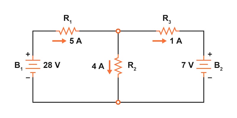
Figure 9. Application of the superimposed current values.
After following all of those steps, it is easy to see how the superposition theorem is quite simple and elegant, don’t you think?
Prerequisites for Using the Superposition Theorem
It’s important to note that the superposition theorem works only for circuits that are reducible to series and/or parallel combinations for each power source evaluated individually. Therefore, for example, it is useless for analyzing an unbalanced bridge circuit.
Another limitation of the superposition theorem is when it is used with linear circuits where all of the underlying equations do not have any mathematical exponents or roots. This is true for most of the circuits we encounter in electrical engineering. A typical circuit built with standard passive components, such as resistors, inductors, and capacitors, is linear. Most voltage sources, batteries, and current sources are also linear to first order. Other network analysis methods, including Thevenin’s theorem and Norton’s theorem, are also limited to use with linear circuits.
Diodes and varistors are examples of non-linear devices because their I-V curves are not linear. At low currents, they can generally be considered linear devices; however, at high currents, a battery may not output a constant voltage, and its function would be non-linear.
The linearity requirement means that the superposition theorem is only applicable for determining voltage and current, not power. Power dissipation, being a nonlinear function, does not algebraically add up to an accurate total when only one source is considered at a time.
Another prerequisite for the superposition theorem is that all components must be “bilateral,” meaning that they behave the same, with current flowing in either direction through them. Resistors have no polarity-specific behavior, thus, the circuits we’ve been studying so far all meet this criterion.
Applications of the Superposition Theorem to AC, DC, and AC/DC Circuits
The superposition theorem finds use in the study of alternating current (AC) circuits and semiconductor (amplifier) circuits, where sometimes AC is often mixed (superimposed) with DC. Since AC voltages and current equations (Ohm’s law) are linear, just like DC, we can use superposition to analyze the circuit with just the DC power source. Then, just the AC power source, combine the results to tell what will happen with both AC and DC sources in effect. For now, though, superposition will suffice as a break from having to do simultaneous equations to analyze a circuit.
Review of the Superposition Theorem
- The superposition theorem states that a circuit with multiple power sources can be analyzed by evaluating only one power source at a time. Then, the component voltages and currents are added algebraically to determine the circuit response with all power sources in effect.
- Step 1: Replace all of the power sources except one. Replace voltage sources with a short circuit (wire) and current sources with an open circuit (break).
- Step 2: Calculate the voltages and currents due to each individual source.
- Step 3: Repeat steps 1 and 2 for each power supply.
- Step 4: Superimpose the individual voltages and currents. Algebraically add the component voltages and currents; paying particular attention to the direction of the voltage drops and current flows.
- The superposition theorem is limited to use with linear, bilateral circuits.
- The superposition theorem can be applied to DC, AC, and combined AC/DC circuits.
- The superposition theorem cannot be used to add power.
Related Content
You can find more information on circuits and the superposition theorem.
Calculators:
Worksheets:
Video Tutorials and Lectures:
Technical Articles:
- Superposition and What it Means For You
- Analyzing Circuits via Source Transformation
- What is a Linear System?


I need help
There is some misplacement of value in the table method for both side as the total current on R2 with applied both source is 5A
why short for voltage sources and open for current sources?