 Facebook
 Google
 GitHub
 Linkedin
Learning to Simplify: Thevenin and Norton Equivalent Circuits
This article reviews the basics of finding Thevenin and Norton equivalents and discusses how to apply Thevenin's theorem to a practical circuit.
Thevenin and Norton equivalent circuits are fundamental approaches to analyzing both AC and DC circuits. It is important to understand the steps involved in converting a circuit to its Thevenin or Norton equivalent, but more important still is understanding how these techniques can help you to analyze and design actual electronic devices.
The Basics
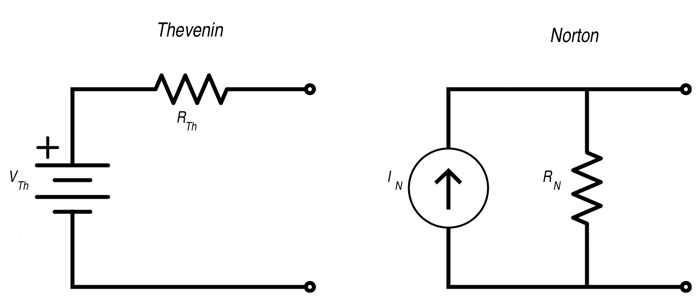
Thevenin’s theorem states that any circuit composed of linear elements can be simplified to a single voltage source and a single series resistance (or series impedance for AC analysis). Norton’s theorem is the same except that the voltage source and series resistance are replaced by a current source and parallel resistance. In this article we will focus on Thevenin’s theorem because the voltage-plus-series-resistance model is more intuitive and more applicable to real-life circuit design. Furthermore, it is easy to convert a Thevenin equivalent to a Norton equivalent and vice versa:
Conversions
|
To Thevenin from Norton |
To Norton from Thevenin |
|
$$R_{Th}=R_N$$ |
$$R_N=R_{Th}$$ |
|
$$V_{Th}=(I_N) (R_N)$$ |
$$I_N=\frac{V_{Th}}{R_{Th}}$$ |
The basic procedure for finding a Thevenin equivalent circuit is the following: First, determine which nodes in your original circuit will correspond to the Thevenin circuit's two output terminals. Second, modify the original circuit so that there is no load connection between these two nodes (for example, by removing a resistor that now corresponds to a load resistor considered external to the circuit). Then, determine VTh by calculating the voltage across the output terminals. Finally, determine RTh by calculating the equivalent resistance assuming all independent sources are removed (this means that voltage sources are replaced by a short circuit and current sources are replaced by an open circuit). For detailed information on how to calcuate a Thevenin or Norton equivalent circuit, see Thevenin’s Theorem or Norton’s Theorem in the textbook section.
Why Thevenize?
The process described above seems simple enough, but calculating the Thevenin equivalent circuit can become quite complicated when the circuit includes numerous components or dependent sources. Also, it is important to keep in mind that the Thevenin equivalent circuit is only an accurate representation of the circuit from the perspective of the load connected to the two output terminals; it doesn’t tell you anything about the internal functionality of the circuit. Even so, there are good reasons for making the effort to figure out a circuit's Thevenin equivalent.
Divide and Conquer
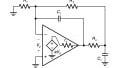
The biggest reason for doing this is that circuits are easier to deal with when they are divided into digestible portions. No one would ever dream of designing a microprocessor by starting with a billion transistors and wiring them together one by one; likewise, even a relatively simple mixed-signal design is best analyzed as a collection of interconnected blocks. This is the essence of Thevenin’s theorem: reduce a circuit to the simplest representation that allows you to determine how that circuit block will interact with another circuit block. Consider the following example:
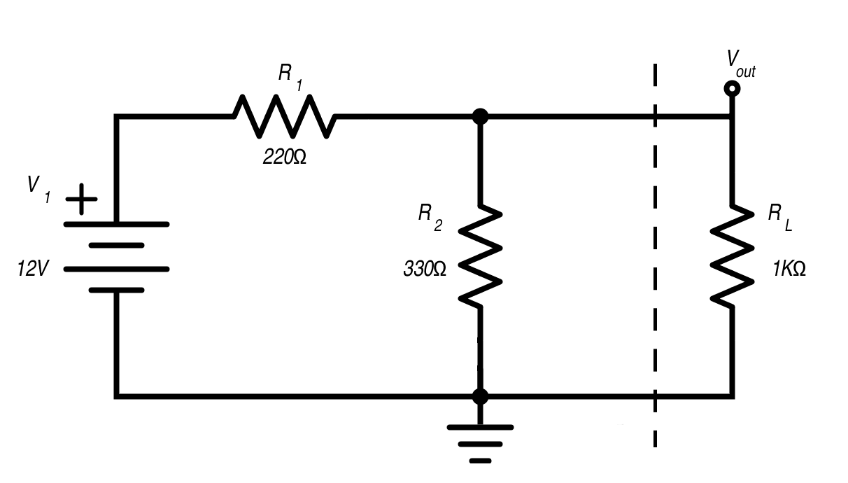
If RL is removed,
$$V_{out}=(12V)(\frac{R_2}{R_1+R_2})=7.2V$$
If RL is included,
$$V_{out}=(12V)(\frac{R_2||R_L}{R_1+R_2||R_L})=6.36V$$
This simple circuit indicates something important related to Thevenin’s theorem: the load affects the circuit. If you remove the load resistor and simply calculate the voltage at Vout, you get 7.2 V. So is it correct to say that the network composed of V1, R1, and R2 is a circuit that supplies 7.2 V to a load resistor? No, because the supplied voltage changes according to the resistance of the load. As shown above, Vout drops to 6.36 V when we insert a 1 kΩ load resistor. With a 100 Ω load resistor, Vout is only 3.1 V. So if you are using the original circuit and you want to know the output voltage for a certain load, you have to repeat the second calculation shown above. If the circuit were more complicated, this task would only get more tiresome. Now we can see the fundamental value of the Thevenin equivalent circuit: it is a simple model that tells you how the original circuit interacts with the load, because the combination of Thevenin voltage and Thevenin resistance ensures that the correct output voltage is provided for all values of load resistance.
Experimental vs. Analytical
One major obstacle to applying the concepts of Thevenin equivalence is the difficulty of determining the Thevenin equivalent voltage and resistance for a complicated circuit. This is especially problematic considering that interesting circuits are generally rather complicated. Fortunately, you can find the Thevenin equivalent experimentally. The first step is to remove the load and measure the open circuit voltage at the output terminals; this is the Thevenin voltage. Next, you need to test the circuit while varying the load resistance until you find the load resistance at which the output voltage is half of the open circuit voltage (you could use a potentiometer here). This load resistance is equal to the Thevenin resistance.
For the simple circuit shown above, here is a plot of output voltage vs. load resistance varied from 1 Ω to 1 kΩ:
.png)
The cursor shows that at 3.6 V (which is half the open circuit voltage), load resistance equals 132 Ω. This agrees with the theoretical Thevenin resistance of
Thevenin's Theorem Applied
Let’s say that we need to design a high-precision circuit that digitizes signals from a sensor whose output voltage varies between 0 and 1 mV. We will use an op-amp to amplify the signal by a factor of 10, then the output from the op-amp circuit will be sent to the analog-to-digital converter. We are considering different ADCs with different input characteristics, and we want to assess how changes in input impedance will affect the output of the op-amp. To do this, we can find the Thevenin equivalent for the op-amp circuit and treat the ADC input impedance as the load resistance. It would be impractical to accomplish this with an actual circuit because op-amps have very low output resistance, but we can get good results with a simulation.
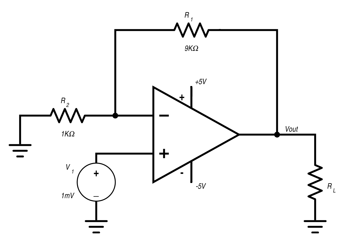
The load resistor is varied from 10 mΩ to 0.5 Ω in steps of 10 mΩ. The gain of this op-amp circuit is 10, so we know that the open circuit output voltage will be 10 mV. Thus, we are looking for the load resistance that gives us an output voltage of 5 mV.
.png)
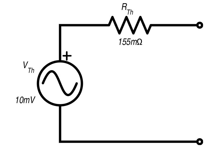
As indicated by the cursor, the output voltage equals half the open circuit voltage at a resistance of 155 mΩ. Notice also that the output voltage levels off at 10 mV once the load resistance is sufficiently large; this confirms our expected value for the open circuit voltage. Now that we know the Thevenin voltage and Thevenin resistance for this op-amp circuit, we can analyze it using a Thevenin equivalent:
Thevenin and Norton Equivalent Circuits
Related Content


Another great one but…how much does this change for AC case with general impedance? Thanks….
How to wire up the foredom fct foot pedal to Dremel 4000 or 4300