Facebook
 Google
 GitHub
 Linkedin
Generation of Alternating Voltage
Video Lectures created by Tim Feiegenbaum at North Seattle Community College.
Generation of Alternating Current
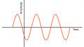
A voltage supplied by a battery or another DC source has a certain polarity and remains constant. We looked at that in our discussion of DC and we looked at battery connected to something and we saw that it had a positive polarity and a negative polarity and it remained constant, it did not change. Alternating current AC varies in polarity and amplitude. Here we see an AC sine wave and we see that it is constantly changing going negative or going positive and then negative. It is alternating.
AC is an important part of electrical and electronic systems. Systems that use alternating current include, 120 volts out of the wall and sometimes this is referred to as 60 cycles because it alternates 60 times a second, during the positive cycle current is falling in one direction and during the negatives cycle, it is falling in the opposite direction. Radio waves for television and radio transmission use alternating current, microwave transmission, Ethernet. All of these are examples of alternating current.
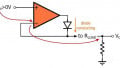
Rectangular Waveshape
Our text starts the alternating current discussion with a very simple circuit that could generate AC. By moving the switch back and forth the output would be an alternating positive and negative value. The switch will be right here and this will be our load and this switch will be the switch between this point and this point. I think your text does this because we have looked at DC and this would be a way of generating an alternating current source. It would not be far from ideal but we could do it this way. By looking at this we get a sense of the movement of current.
Let's take a look at this first. If the switch is in this position, notice we are connected to the positive battery. Remember current is flowing from negative to positive so from the negative side of this battery we will come down through the ground remember that through the ground that is the same electrical point. Coming from the negative side we will come down and our flow will be up through the resistor to the positive side of the battery. This will be our direction of our current flow and the current will be coming up through the resistor to the positive side of this battery and that would give us the positive side of this wave shape.
Now, when we pull this switch down and now we have it connected to this point here across here, notice now we are connected to a battery but we're connected to the negative side. Current is going to flow again through here, it's going to come through here and now it's going to go across the switch because it's pulled down now. It's going to go down the resistor and then this is a little bit confusing it looks like a figure aid, but this would be the path for current.
The difference here is that now notice the current is flowing down through the resistor rather than. In this particular configuration that is where we are going to be generating the negative part of this square wave. Point being that when you have the positive part of alternating wave the current is going one direction, when you have the negative it's going the opposite direction, current is constantly changing direction in alternating current. By its very name alternating current gives you the sense that current is changing direction. If we're thinking about 60 cycles household current, that current is changing directions 60 times per second.
Alternating currents are repetitious and consist of a continuous series of cycles. Here we have an example, continuous series of cycles. The time for one complete cycle is called the period of the waveform. Here we have one complete cycle and that is referred to as a period. A period consists of two opposite polarity alternations. Here we have one going negative, one going positive and that makes up one complete period.
If the positive and negative waveforms are equal it is symmetrical and we are talking about alternating current AC out of the wall. It is symmetrical if not it is asymmetrical. The rectangular signal above is a digital signal, the abrupt changes in polarity are necessary for digital circuits.
Sine Wave Characteristics
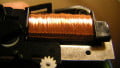
The basis of an AC alternator or generator is a loop of wire rotated in a magnetic field. Here we have a coil of wire that is rotating and it is very important to remember that it is rotating. It is connected through a shaft and there are slip rings and brushes that will be the contact point for taking the voltage off of this coil. You see here the relative movement of that coil, you see the North and the South pole magnets and you see this coil of wire that is being turned and in the process of turning, we're generating an AC signal.
Now, we could go over...let me just go over to this link right here. This particular site called Molecular Expressions. They have a lot of simulations this is a Job simulation. By the way, if you go on this you will have to have a Job on your machine you may have to install that if you go to this particular link. Okay, let's take a look at what's going on here. Here we have an AC generator, you will notice that the coil of wire is turning inside the magnetic field, you'll notice here are the slip rings and they are turning. You will notice the brushes are connected to the slip rings and one end of this coil is connected to one side of this ring and the other side of the coil is connected to this ring.
The difference is potential between these two points is what we are seeing on the meter. You see this is measuring voltage and you notice that the voltage is swinging from positive to negative and back and forth. You also see the sine wave that will be generating, you can see that it is alternating positive to negative, positive to negative and we have our characteristic sine wave here.
If we were to increase the frequency here or increase the speed of coil you will notice that the faster that this coil turns the larger is the sine wave. It isn't just that the frequency increases actually the amplitude, the actual voltage is increasing. If I crank this way up you can see this is getting near, it was almost pegging the meter going both directions.
That's the principle of AC generation that the coil must be moving in the magnetic field to generate a voltage and the faster that it moves the larger the voltage it will be generating. This is because the coil is cutting more magnetic flux lines.
Here we just took a look at an example of the slip rings and the brushes and we saw the turning of the coil in the magnetic field. Let's see this is just a repetition from what we just looked at there is the loop of wire this is just a little bit bigger picture. Slip rings brushings as the conductor and the coil rotates waveforms are generated.
Okay, the magnitude and polarity of the generated voltage will be shown in the next slide. Okay, here we have a little more detailed analysis of what is going on. Here we have the rotating coil at zero degrees below, note the conductors are parallel with the flux lines and no voltage is generated. Here we see the coil is parallel with our North and South poles and now we're at zero degrees.
At nine degrees the conductor is cutting a maximum number of flux lines and generates voltage B. You see, let's remember the blue side of this coil and the black side, the blue is over here toward the North side, we are at 90 degrees we are generating sine wave B. At 180 degrees we are at the same situation we were at zero. Notice again the coil is parallel again and we are at zero volts. At 270 the conductor is again cutting the maximum number of flux lines.
Except the polarity has shifted and the voltage is now negative. Here notice, we look like this, except notice that the blue is over here in the South, here it was north and now we are generating our negative signal and we are 270 degrees. At 360 degrees right here, we return to 0 degrees and a new cycle starts again. If we were generating AC for home use, this cycle represents 60 times, we repeat 60 times per second.
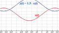
Here we have some sine wave characteristics. The sine wave at the right consists of two opposite polarity alternations. Here we go, here is one polarity, positive polarity, then here is the negative polarity alternation. Each alternation is called a half cycle. That because it is half and half, here is one complete cycle so obviously this is positive is half, negative this is half. Each half cycle has a maximum value called the peak value. You'll notice here from this flat line in the middle, it represents 0 volts so we have a peak value from zero to this peak and from the negative going from here to here.
Now, I have a simulation with electronics work bench. Let's take a quick look at it. Here we have a 1Volt, 60 Hertz signal. I've got this oscilloscope connected to it and we see the sine wave. If I activate this let's see if we can make it go. Okay here we go, and we see the sine wave being generated and we are measuring it on the oscilloscope. Great, okay ignore that that was a computer glitch. Didn't expect that to happen, okay let's continue.
Here we have our 1Volt, 60 Hertz signal being generated and we are looking at it here on the O-scope. If we were to, why don't we pause this and let's take a little bit closer look if we go to, let's just go to this point right here. Then we'll move this point over to right here so that we are looking at one cycle and down here, we see the time between the two points between one and two.
You'll notice it is 16.7, it probably should be 16.6 milliseconds because that we don't know we'll have a little trouble getting the 16.6 exactly. But 16.6 would be the time of one cycle. If you take one divided by 60, you will get 16.6 milliseconds and that is the time of one cycle. Remember that in AC, in one cycle the voltage will go or half the cycle goes positive, half the cycle negative does this 60 times per second. In this particular presentation, we looked at sine wave characteristics. We looked at the various points of the sine wave that is being generated by the rotating coil. We also looked at the simulation.
You might want to note that, you are [lucky 0:13:59] if you want to go there and do that on your own. We looked at the generation of rectangular wave shapes and we looked at a battery. Two batteries that could generate a rectangular wave which is functional if there is AC we wouldn't usually generate it this way. But this was a way of introducing alternating current.
Related Content