Facebook
 Google
 GitHub
 Linkedin
20A (Single Voltage) or 10A (Dual Voltages): A DC/DC Voltage Regulator Module from Linear Technology
A compact μModule point-of-load regulator from Linear Technology can be configured as either a single 20-amp voltage regulator or two 10-amp voltage regulators.
A compact μModule point-of-load regulator from Linear Technology can be configured as either a single 20-amp voltage regulator or two 10-amp voltage regulators.
Linear Technology, now part of Analog Devices, recently released the LTM4646, which they describe as a compact dual 10 A or single 20 A step-down μModule point-of-load (POL) regulator. According to the datasheet, with the exception of some external capacitors and resistors (see the figure below), this step-down voltage module is characterized as being a complete solution, meaning that it includes the inductors, the switches (MOSFETs), the DC/DC controller, and the associated supporting components.

The LTM4646 requires only a few external passive components for operation—the inductors and MOSFETs are included in the module. Image taken from Linear.com.
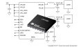
Although this IC, based on the figure above, may appear to be rather simple to implement, adding it to a PCB may require some extra care given that it's housed in an 88-pin BGA package (see the figure below).

This BGA package type may test your PCB layout skills. Image taken from the datasheet.
Single 20 A or Dual 10 A Configuration
According to the section titled VOUTS1, VOUTS2 (G2, E2) on page 8 of the datasheet, configuring this module for operation as a single-channel voltage regulator that is capable of sourcing 20 A, you need to allow the VOUTS1 pin to float whilst connecting the VFB1 pin to INTVCC. The figure below depicts this arrangement.

This circuit, from the datasheet, shows how the IC is configured for a single 20 A voltage channel.
Additional typical application examples can be found on pages 28 to 31 of the datasheet.
Efficiency Levels up to 96%
Depending on voltage input and voltage output values, this IC may or may not be able to achieve its touted high efficiency of 96%. For example, if a design requires a VIN of 5 V along with a VOUT of 3.3 V, then attaining 96% is feasible (see the figure below).
_efficiency_curve-1_(1).jpg)
With a VIN of 5V, a VOUT of 3.3V yields the highest efficiency level. Image taken from the datasheet.
However, if the input voltage is closer to 12 V with an output voltage of around 0.9 V, then it appears, judging from the figure below, that an efficiency of 85% is the highest that can be accomplished. So, if achieving high efficiency is a priority according to your design specifications, then be sure to review the efficiency curves to ensure that your design requirements permit this IC to deliver acceptable efficiency levels.

With an input voltage of 12V, only ~85% efficiency can be attained with a VOUT of 0.9V. Image taken from the datasheet.
While this regulator module is characterized—in the section titled Power Module Description (on page 11)—as able to provide high efficiencies at light loads by use of the pulse-skip feature, the device’s efficiency curves do not indicate if the data reflects pulse-skip operation or normal operation. If high efficiency at light loads is an important requirement in your application, you might want to contact Linear Tech and ask for details.
Output Voltage Programming
While only a single resistor is required for setting the output voltage of channel one (VOUT1), channel two (VOUT2) requires the use of two resistors. In addition to providing equations for calculating the values of all three resistors (see the figure below), the datasheet also includes a table of resistor values for "various output voltage" levels (see the subsequent figure below). So, if you're lucky enough to find acceptable output voltage levels listed on this table, then you get to opt out of the math exercise.

Determining the resistor values for setting VOUT1 and VOUT2 can be determined with these equations. From the datasheet.

Instead of using your math skills, this table may be helpful...depending on your desired VOUT values. Table taken from the datasheet.
A Demo Board is Available
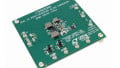
If you'd like to test this new compact μModule point-of-load regulator before taking the time to design a new PCB, then consider getting the LTM4646 demo board. Conveniently, in addition to providing a demo board manual, Linear Tech provides the demo board's design files and schematics.

A demo board is available for the LTM4646. Image courtesy of Linear.com.
Have you had a chance to use this new compact dual 10A or single 20A μModule regulator, the LTM4646, from Linear Technology? If so, leave a comment and tell us about your experiences.
Related Content