 Facebook
 Google
 GitHub
 Linkedin
AC vs. DC (Alternating Current vs. Direct Current) Electrical Signals
In this article, we'll cover the essential place of signals in circuits design, define AC and DC signals, and discuss the source of AC and DC power-supply voltages.
Introduction to Signals
Electrical engineers spend a lot of time talking about signals. The original meaning of this word is closely related to the concept of transmission and reception: a signal was any type of gesture, sound, or mechanical movement used to convey information. Nowadays, it is a generic engineering term that we use when referring to voltages, currents, numerical sequences, and mathematical expressions that vary with respect to time. It’s important to recognize, though, that these signals maintain a conceptual connection with transmission and reception, because they are, in general, a means of transferring or representing information.
The characteristics of an electrical signal are determined by its relationship between amplitude and time. This relationship can be captured by mathematical expressions and by sequences of data points, but in many cases, the most concise, convenient, and informative method is a visual representation. We often analyze signals by way of graphs in which the vertical axis indicates amplitude and the horizontal axis indicates time. The result is a curve whose changes in vertical position correspond to a signal’s variations in voltage or current. For example:

Alternating Current and Direct Current
Electrical signals come in an endless variety of shapes and sizes. However, if we focus on general characteristics, we can group signals into broad categories. Perhaps the most fundamental categorization is that of DC versus AC.
DC stands for “direct current,” and AC stands for alternating current. Current is direct if it always flows in the same direction, whereas alternating current periodically changes direction. The terms “DC” and “AC” have become generic adjectives that can describe voltages and even currents (we often say “DC current” instead of “direct current”). Thus, “DC voltage” is not really interpreted as “direct-current voltage”; rather, it indicates that the voltage does not change polarity—the amplitude may exhibit large variations over time, but it is always positive or always negative. An AC voltage, on the other hand, consistently changes from positive polarity to negative polarity and from negative polarity to positive polarity.
AC and DC Signals
The terms AC and DC can describe signals as well. An AC signal is a current, voltage, or numerical sequence that consistently exhibits both positive and negative values, and a DC signal exhibits only positive values or only negative values.
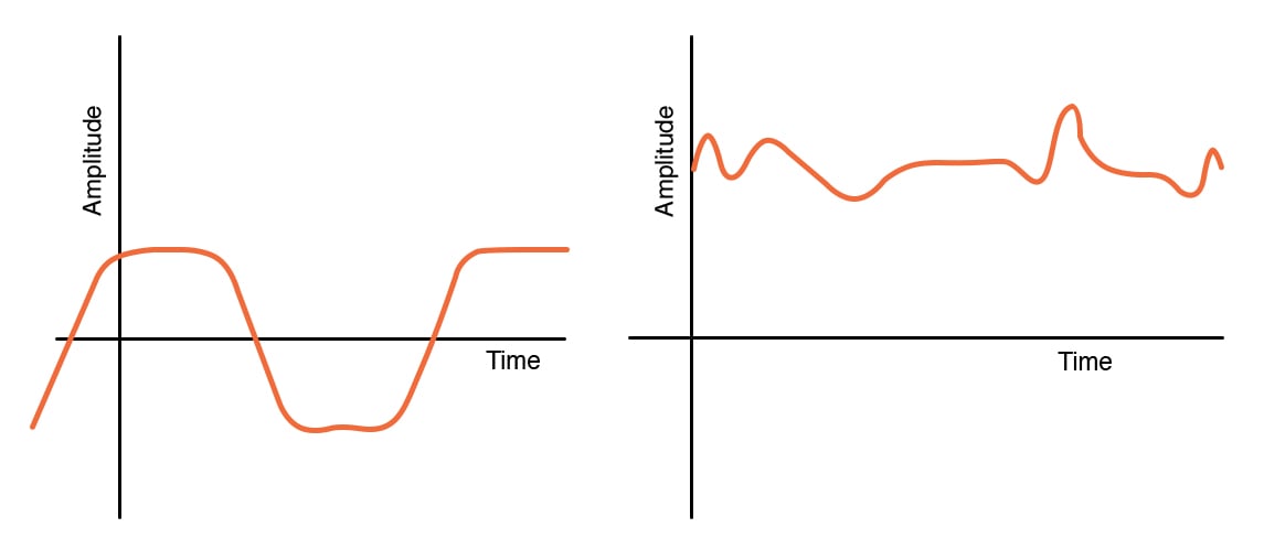
The following plots provide examples of AC and DC signals. The signal on the left is AC; the voltage regularly extends above and below the horizontal axis, which corresponds to an amplitude of 0 V. The signal on the right is DC; it has significant variations in amplitude, but the voltage is always in the positive portion of the graph.
AC and DC Sources
The terms “AC” and “DC” are closely associated with power-supply voltages. These voltages are generated by sources and are a means of injecting electrical energy into a circuit. Despite the fact that AC supply voltages always vary with respect to time, we generally don’t refer to them as signals. This makes sense because their purpose is to supply energy rather than represent or transmit information.
The two most common sources of electrical energy are generators and batteries. Generators are AC sources; they produce sinusoidal voltages that periodically vary between positive polarity and negative polarity. Batteries create a static potential difference between two terminals, and consequently, they are DC sources. In circuit diagrams, DC and AC voltage sources can be represented by the following symbols:

Electrical energy is distributed through the power grid as alternating current, but electronic systems require DC supply voltages. An AC supply voltage can be converted into a stable DC supply voltage by means of a rectifier followed by a voltage regulator. We’ll learn more about AC-to-DC conversion and voltage regulation in future video tutorials.
Conclusion
We have covered the basic characteristics of electrical signals and the difference between AC and DC with regard to signals and supply voltages. The next two video tutorials will explore the ways in which electrical systems use DC and AC signals.


I’m so glad this site exists, I’m able to learn a ton of stuff that I’ve forgotten over the years