 Facebook
 Google
 GitHub
 Linkedin
Capacitors and Capacitance vs. Inductors and Inductance
In a previous video tutorial, we saw that voltage and current sources provide the energy that allows an electrical circuit to carry out its intended functionality. However, a circuit is not simply divided into sources that supply energy and components that consume energy. In fact, two common electronic components—the capacitor and the inductor—naturally store energy. These components can function as temporary energy sources, and they are widely used in power networks, voltage-regulator circuits, and frequency-dependent circuits called filters.
Capacitors and Capacitance
Capacitance exists wherever conductive material is separated by insulating material. Capacitive structures have the ability to store energy as an electric field; when a capacitive structure has been designed as an electrical component that has a specified amount of capacitance, it is called a capacitor.
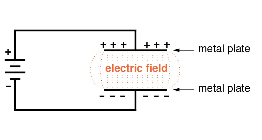
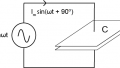
We use the terms charging and discharging to identify, respectively, a state in which the capacitor is gaining energy and a state in which the capacitor is supplying energy. As shown in the diagram, we can charge a capacitor by connecting it to a battery. The voltage causes current to flow, and this current delivers electric charge to the capacitor. The accumulation of charge creates a voltage across the capacitor that gradually increases as the current flowing in the circuit gradually decreases. If the charged capacitor is disconnected from the battery and connected to a resistor, it functions as a voltage source because the energy stored in the electric field can convert accumulated charge into moving charge—in other words, electric current.
The voltage and current behavior associated with a charging capacitor is conveyed by the curves in the following diagram. Note that the time axis uses the abbreviation “RC”; this refers to the RC time constant, that is, a period of time corresponding to the capacitance (denoted by C) of a capacitor multiplied by the resistance in series with the capacitor.
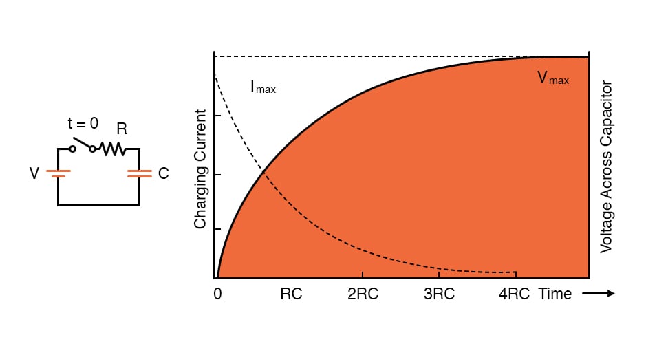
A component’s capacitance is a critical circuit-design parameter because, as indicated by the diagram, it influences the rate at which voltage (or current) changes during charging and discharging. Higher capacitance means that the voltage across a capacitor will increase more slowly (when it is charging) and decrease more slowly (when it is discharging).
Quantifying Capacitance
When electrical engineers incorporate capacitance into a schematic, they have to choose a capacitor with the proper capacitance value. A capacitor with higher capacitance can store more charge per given amount of voltage. We use the unit farad, which corresponds to coulombs per volt, to quantify capacitance. If a 2 µF capacitor and a 20 µF capacitor have both been charged up to the same voltage, the 20 µF capacitor will have ten times more stored charge than the 2 µF capacitor.
Inductors and Inductance
If you are comfortable with the basic concepts of capacitance, you are well on your way to understanding inductance, because these two phenomena are very similar—they might be described as “equal but opposite”:
- A capacitor stores energy in an electric field; an inductor stores energy in a magnetic field.
- When a capacitor is connected to a voltage source, its voltage gradually increases and its current gradually decreases; when an inductor is connected to a voltage source, its current gradually increases and its voltage gradually decreases.
- With a capacitor, the rate of charging and discharging is governed by the RC time constant; with an inductor, we use the RL time constant, which is inductance (L) multiplied by the resistance in series with the inductor.
- If a capacitive circuit is disconnected from a power supply, the capacitor will temporarily maintain voltage. If an inductive circuit is disconnected from a power supply, the inductor will temporarily maintain current. Another way of saying this is that capacitors “resist” changes in voltage and inductors “resist” changes in current.
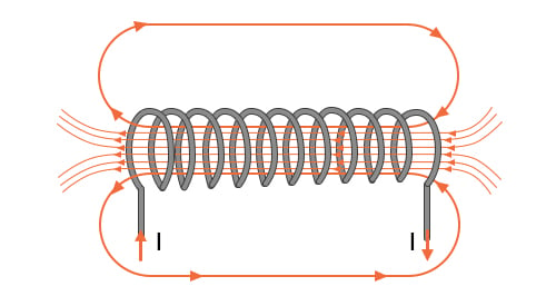
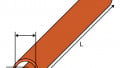
All conductors, such as wires and component pins, have inductance. To create an inductor, we use techniques that strengthen a magnetic field and thereby increase inductance. A basic inductor is simply a coiled wire; the following diagram conveys the way in which this structure concentrates magnetic field lines.
Quantifying Inductance
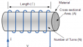
Inductance indicates the amount of voltage that will be generated by an inductor as a result of changes in the rate of charge movement through the inductor. It is measured using a unit called the henry.
Recap
- Capacitors and inductors are electronic components that can store energy supplied by a voltage source.
- A capacitor stores energy in an electric field; an inductor stores energy in a magnetic field.
- Voltages and currents in a capacitive or inductive circuit vary with respect to time and are governed by the circuit’s RC or RL time constant.
Related Content


Resistance