 Facebook
 Google
 GitHub
 Linkedin
Characteristics and Applications of DC (Direct Current) Signals
In the previous video, we explained the meaning of the word “signal” in the context of electrical engineering, and we introduced two broad categories—namely, AC and DC—that appear very frequently in discussions of power supplies, components, and circuits. Now it’s time to take a closer look at DC signals.
What Do Real-Life DC Signals Look Like?
The fundamental characteristic of a DC signal is the absence of changes in polarity. If you connect a DC voltage signal to a resistor, the resulting current will always flow in the same direction. The magnitude of the current may exhibit large variations, but the direction does not change.
Some of the most common DC voltages are supply voltages generated by regulator circuits, and consequently, some people might associate the term “DC” with voltages or currents that are completely stable and constant. However, this is not the case.
First of all, voltages are never perfectly constant, even when we want them to be, because all signals include noise. Second, some DC signals cover a wide (though unipolar) range of amplitudes because they are influenced by highly variable external conditions. Let’s explore these two aspects of DC signals more thoroughly.
Electrical Noise
We use the word “noise” to identify undesired (and usually small) variations in voltage and current. All DC (and AC) signals contain noise because it is generated by inescapable physical processes. When we say that a DC signal has an amplitude of 5 V, we really mean that the average amplitude or the desired amplitude is 5 V. If you carefully measure this signal, you will see that the amplitude is constantly moving above and below 5 V.

This image shows two measured signals with different noise characteristics.
It is not surprising to learn that engineers prefer signals with smaller amounts of noise. However, it’s important to understand that noise amplitude itself is less important than the amplitude of the noise relative to the amplitude of the signal. This is why we frequently express the quality of a signal by means of the signal-to-noise ratio, abbreviated SNR.
Electrical engineers must always be mindful of the presence and potential effects of noise, even in supply voltages and slowly varying DC signals. For much more information on this interesting topic, please refer to AAC’s article on the nature and origins of electrical noise.
Ripple
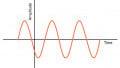
One very common type of noise found in DC voltages is the ripple generated by switch-mode regulators. The word “ripple” refers to small, periodic variations associated with the regulator’s on/off switching action. The image below is a measured signal that exhibits switching ripple as well as two other types of noise.

DC Sensor Signals
We often encounter DC signals when we are working with sensors. These components generate voltage or current signals that allow us to monitor, analyze, and record physical conditions and aspects of the surrounding environment. Conditions such as humidity, light intensity, and absolute temperature are highly variable but unipolar (for example, light intensity cannot be lower than zero), and the voltage or current produced by the sensor is, therefore, a DC signal.
Applications of DC Voltage and Current
We’ve already seen that DC voltages are used to supply electrical power for electronic circuitry and to represent changes in physical variables. DC quantities also appear in the following applications:
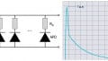
- DC current limited by a resistor causes light-emitting diodes (LEDs) to produce light.
- Mechanical and electronic switches can deliver large amounts of DC control current to motors, solenoids, and resistive heaters.
- DC currents and voltages establish the electrical conditions that allow transistors to amplify AC signals.

The same basic switch circuit is controlling a high-intensity LED (on the left) and a relay (on the right) by allowing or preventing the flow of DC current.
Conclusion
DC signals and power-supply voltages are essential aspects of countless electronic systems, but electrical engineers must also be thoroughly familiar with AC signals and with the techniques that are used to analyze and design AC circuits. We’ll study alternating current in the next video.
Related Content


Nice lesson