 Facebook
 Google
 GitHub
 Linkedin
Nodal Analysis and Dependent Sources
The use of dependent sources when using Nodal Analysis.
The use of dependent sources when using Nodal Analysis.
Recommended Level
Beginner
Nodal Analysis
Nodal analysis is a form of analysis that uses Kirchhoff’s Current Law (KCL) and node equations to solve for circuit voltage values where the schematic diagram does not have any conductor paths crossing. A term typically used for this purpose is said to represent a planar circuit.
This is used to determine the voltage at each node( or connection point of two or more components) with respect to a reference node. The reference node is frequently called ground where the voltage at ground is equal to zero Volts.
In viewing schematic diagrams with either voltage sources or current sources, a reference node would usually be assigned to the negative terminal for a voltage source and to the opposite end when an arrow is shown for a current source. Another method of selecting the reference node would be to select the middle node when viewing all nodes.
There are two kinds of electrical sources: 1) independent and 2) dependent.
An independent source provides a fixed value of voltage or current to the connected circuit. Independent sources are power supplies and batteries. Power supplies provide a constant fixed value whereas batteries will not provide a constant fixed value over time without recharging them.
A dependent source is either a voltage source or current source whose value depends upon a voltage or current value somewhere else in the circuit. Dependent sources are useful tools in analyzing amplifiers. Two characteristics of amplifiers are voltage gain (AV) and current gain (Ai). There are four basic linear dependent sources:
1. Voltage-controlled voltage source where the output is V, and AV is the constant of proportionality (voltage gain), and VCD is the parameter being sensed. The following equation is associated with a voltage-controlled voltage source:
$$V = A_{V}V_{CD}$$
2. Current-controlled voltage source where the output is V, and RM is the constant of proportionality (resistance), and IC is the parameter being sensed. The following equation is associated with a current-controlled voltage source:
$$V = R_{M}I_{C}$$
3. Current-controlled current source where the output is I, and Ai is the constant of proportionality (current gain), and IC is the parameter being sensed. The following equation is associated with a current-controlled current source:
$$I = A_{I}I_{C}$$
4. Voltage-controlled current source where the output is I, and GM is the constant of proportionality (conductance), and VCD is the parameter being sensed. The following equation is associated with a voltage-controlled current source:
$$I = (G_{M})(V_{CD})$$
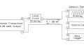
A nodal analysis with a dependent source occurs when there are two DC voltage sources and a DC current source as shown in Figure 1. Note the value for E1 is expressed in terms of an unknown value. E1 = 2Vx. Note that the voltage across resistor R1 is expressed as Vx. Note that the voltage across resistor R3 is expressed as V0. This information is to be used later in calculating node voltages.
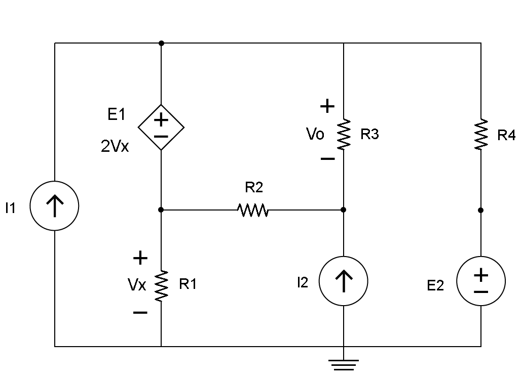
Fig. 1
If the node or test point voltage were positive, it would read a positive value on the voltmeter. If the node or test point voltage were negative, it would read a negative value on the voltmeter.
An example problem for the circuit shown in Figure 1 would be to find the following:
A. The voltage across resistor R3 (V0).
B. The current through resistor R1 (IR1), R2 (IR2), R3 (IR3) and R4 (IR4).
C. Let I1 = 2 mAmps, I2 = 2 mAmps, E1 = 2Vx, E2 = 4 Volts, R1 = 1 Kilo Ohms, R2 = 2 kilo Ohms, R3 = 3 kilo Ohms, and R4 = 4 kilo Ohms.
D. Let the voltage across R1 (ER1) = Vx and E1 = V1 – V2.
The 1st step would be to identify the reference node or ground and then all the nodes of the circuit in Figure 1. Usually any independent source would be connected to ground and is shown in Figure 1.
In this circuit, there are nodes at the top of DC voltage source E1 labeled V1, below E1 labeled V2, below resistor R3 labeled V3, and above DC source E2 labeled V4. These nodes are shown in Figure 2.
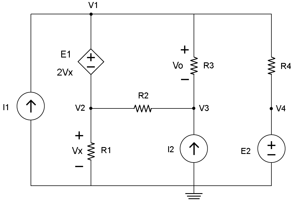
Fig. 2
The 2nd step would be to identify the super node, which has the dependent source with an unknown value of E1 that is equal to 2Vx. Draw a red line around V1 and V2 that has E1 within as shown in Figure 3.
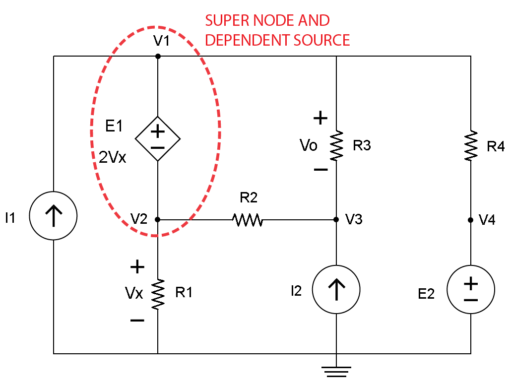
Fig. 3
The 3rd step would be to determine the independent source, which are the voltage source E2, and current sources I1 and I2. Draw a blue line around V4 and E2, I1 and I2 as shown in Figure 4.
-b-01.png)
Fig. 4
The 4th step is to identify currents at the super node with a blue line and arrow labeled a, b, c, d and e as shown in Figure 5.
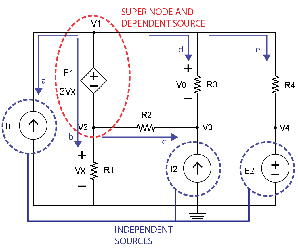
Fig. 5
The 5th step is to identify currents at the V3 node with a red line and arrow labeled f, g and h as shown in Figure 6.
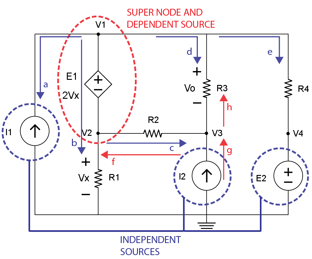
Fig. 6
The next step will utilize Figure 5 that identifies the super node so Kirchhoff’s Current Law (KCL) equations can be identified. Remember, Kirchhoff’s Current Law (KCL) states the algebraic sum of all currents entering and exiting a node must equal zero.
The following KCL current equations can be written for the blue lines and arrows at the super node for a, b, c, d and e:
$$ -I_{1} + I_{b} + I_{c} + I_{d} + I_{e} = 0 $$
Note that:
$$ I_{b} = \frac{V_{2}}{R_{1}}, I_{c} = \frac{V_{2}-V_{3}}{R_{2}}, I_{d} = \frac{V_{1}-V_{3}}{R_{3}}, I_{e} = \frac{V_{1}-E_{2}}{R_{4}} $$
The equation now becomes:
$$ -I_{1} + \frac{V_{2}}{R_{1}} + \frac{V_{2}-V_{3}}{R_{2}} + \frac{V_{1}-V_{3}}{R_{3}} + \frac{V_{1}-E_{2}}{R_{4}} = 0 $$
Substitute circuit values:
$$ -(\text{2 m}) + \frac{V_{2}}{\text{1 k}} + \frac{V_{2}-V_{3}}{\text{2 k}} + \frac{V_{1}-V_{3}}{\text{3 k}} + \frac{V_{1}-E_{2}}{\text{4 k}} = 0 $$
Multiply both sides by 12 k (Least Common Denominator):
$$ [-(\text{2 m}) + \frac{V_{2}}{\text{1 k}} + \frac{V_{2}-V_{3}}{\text{2 k}} + \frac{V_{1}-V_{3}}{\text{3 k}} + \frac{V_{1}-E_{2}}{\text{4 k}} = 0] (\text{12 k}) $$
Expand:
$$-24 + 12V_{2} + 6(V_{2} – V_{3}) + 4(V_{1} – V_{3}) + 3(V_{1} – 4) = 0$$
$$-24 + 12V_{2} + 6V_{2} – 6V_{3} + 4V_{1} – 4 V_{3} + 3V_{1} – 12 = 0$$
Combine terms:
$$7V_{1} + 18V_{2} – 10V_{3} = 36$$ [Equation 1]
The next step will utilize Figure 6 that shows the currents at the V3 node so the equations can be written for the red lines and arrows for f, g and h. Please note the directions of currents through resistor R2 and R3 are opposites when viewing the blue and red lines and arrows for c and g, and for d and h. This will be important later on in checking results.
$$ -I_{2} + \frac{V_{3} - V_{2}}{R_{2}} + \frac{V_{3}-V_{1}}{R_{3}} = 0 $$
Substitute circuit values:
$$ -(\text{2 m}) + \frac{V_{3} - V_{2}}{\text{2 k}} + \frac{V_{3}-V_{1}}{\text{3 k}} = 0 $$
Multiply both sides by 6 k (Least Common Denominator):
$$ [-(\text{2 m}) + \frac{V_{3} - V_{2}}{\text{2 k}} + \frac{V_{3}-V_{1}}{\text{3 k}} = 0 ] (\text{6 k}) $$
Expand:
$$-12 + 3(V_{3} – V_{2}) + 2(V_{3} – V_{1}) = 0$$
$$-12 + 3V_{3} – 3V_{2} + 2V_{3} – 2V_{1} = 0$$
Combine terms:
$$-2V_{1} – 3V_{2} + 5V_{3} = 12$$ [Equation 2]
There are two equations and three unknowns. Another equation is needed. When reviewing Figure 5 the given information concerning the DC voltage source E1 and nodes V2 and the voltage across resistor R1 that is Vx, another equation can be obtained.
Fig. 5
The following information is known:
$$E_{1} = V_{1} – V_{2}$$
$$E_{1} = 2V_{X}$$
$$V_{1} – V_{2} = 2V_{X}$$ [Equation A]
$$V_{2} = V_{X}$$ [Equation B]
Using Equation B with V2 = Vx in Equation A, another equation for V1 can be obtained:
$$V_{1} – V_{2} = 2V_{X}$$
$$V_{1} – V_{X} = 2V_{X}$$
Solve for V1:
$$V_{1} = 2V_{X} + V_{X}$$
$$V_{1} = 3V_{X}$$ [Equation 3]
Now Equation 1 and Equation 2 need to have the V1 and V2 terms in terms of Vx and V3 by using Equation A and Equation B:
Recall Equation 1: $$7V_{1} + 18V_{2} – 10V_{3} = 36$$
$$7(3V_{X}) + 18(V_{X}) – 10V_{3} = 36$$
$$21V_{X} + 18V_{X} – 10V_{3} = 36$$
$$39V_{X} – 10V_{3} = 36$$ [Equation C]
Recall Equation 2: $$-2V_{1} – 3V_{2} + 5V_{3} = 12$$
$$-2(3V_{X}) – 3(V_{X}) + 5V_{3} = 12$$
$$-6V_{X} – 3V_{X} + 5V_{3} = 12$$
$$-9V_{X} + 5V_{3} = 12$$ [Equation D]
Now there are two equations and two unknowns that can be solved.
$$39V_{X} – 10V_{3} = 36$$ [Equation C]
$$-9V_{X} + 5V_{3} = 12$$ [Equation D]
When 2 is multiplied on both sides of Equation D, the two equations could be added together causing the V3 terms to cancel leaving one equation with one unknown.
Multiply both sides of Equation D by 2:
$$(-9V_{X} + 5V_{3} = 12) (2)$$
Expand:
$$-18V_{X} + 10V_{3} = 24$$ [Equation D]
Add the new Equation D to Equation C:
$$39V_{X} – 10V_{3} = 36$$ [Equation C]
$$-18V_{X} + 10V_{3} = 24$$ [Equation D]
$$21V_{X} = 60$$
Solve for Vx:
$$\underline{V_{X} = 2.86 \text{ v}}$$
Recall: $$V_{2} = V_{X}$$, Substitute $$V_{X} = 2.86 \text{ volts}$$
$$\underline{V_{2} = 2.86 \text{ v}}$$
Recall: $$V_{1} = 3V_{X}$$, Substitute $$V_{X} = 2.86 \text{ volts}$$
$$V_{1} = 3(2.86 \text{ v})$$
$$\underline{V_{1} = 8.58 \text{ v}}$$
When Equation 1 and the calculated values for V1 and for V2 are used, V3 can be calculated:
Recall: $$7V_{1} + 18V_{2} – 10V_{3} = 36$$
Substitute values for V1 and for V2:
$$7(8.58) + 18(2.86) – 10V_{3} = 36$$
Expand:
$$60.06 + 51.48 – 10V_{3} = 36$$
Combine terms:
$$111.54 – 10V_{3} = 36$$
Solve for V3:
$$-10V_{3} = -111.54 + 36$$
Divide both sides by –10:
$$\underline{V_{3} = 7.55 \text{ v}}$$
The value of V0 can be calculated by using Figure 5:
Recall: $$V_{0} = V_{1} – V_{3}$$
Substitute values for V1 and for V3:
$$V_{0} = 8.58 \text{ v} – 7.55 \text{ v}$$
$$\underline{V_{0} = 1.03 \text{ v}}$$
Now that all node voltages are known, currents can be calculated for resistor R1 (IR1), R2 (IR2), R3 (IR3) and R4 (IR4).
Recall: $$I_{R_{1}} = \frac{V_{2}}{R_{1}}$$
$$I_{R_{1}} = \frac{2.86 \text{ v}}{\text {1 k }\Omega}$$
$$\underline{I_{R_{1}} = 2.86 \text{ mA}}$$
Recall: $$I_{R_{2}} = \frac{V_{2} – V_{3}}{R_{2}}$$
$$I_{R_{2}} = \frac{2.86 \text{ v} – 7.55 \text{ v}}{\text {2 k }\Omega}$$
$$\underline{I_{R_{2}} = -4.69 \text{ v}}$$
$$\underline{I_{R_{2}} = -2.35 \text{ mA}}$$
Recall: $$I_{R_{3}} = \frac{V_{1} – V_{3}}{R_{3}}$$
$$I_{R_{3}} = \frac{8.58 \text{ v} – 7.55 \text{ v}}{\text {3 k}\Omega}$$
$$I_{R_{3}} = \frac{1.03 \text{ v}}{\text {3 k}\Omega}$$
$$\underline{I_{R_{3}} = 0.34 \text{ mA}}$$
Recall: $$I_{R_{4}} = \frac{V_{1} – V_{4}}{R_{4}}$$
$$I_{R_{4}} = \frac{8.58 \text{ v} – 4 \text{ v}}{\text {4 k}\Omega}$$
$$I_{R_{4}} = \frac{4.58 \text{ v}}{\text {4 k}\Omega}$$
$$\underline{I_{R_{4}} = 1.15 \text{ mA}}$$
To confirm KCL current calculations, consider those associated at the super node:
$$- I_{1} + I_{R_{1}} + I_{R_{2}} + I_{R_{3}} + I_{R_{4}} = 0$$
Substitute circuit values:
$$(-2 \text{ mA}) + 2.86 \text{ mA} - 2.35 \text{ mA} + 0.34 \text{ mA} + 1.15 \text{ mA} = 0$$
Combine terms:
$$4.35 \text{ mA} – 4.35 \text{ mA} = 0$$
To confirm KCL current calculations at the V3 node:
$$-I_{2} + I_{R_{2}} + I_{R_{3}} = 0$$
Note IR2 and IR3 are opposites signs from the super node calculations
$$(-2 \text{ mA}) + 2.35 \text{ mA} – 0.34 \text{ mA} = 0$$
Combine terms:
$$(-2.34 \text{ mA}) + 2.35 \text{ mA} \approx 0$$
A voltage controlled current source is where the output current (IS) is a linear function of a connected component that has a referenced voltage (VX) in the following relationship:
IS = (A) (IX) Where A is a multiplier and IX needs to be determined.
The following diagram of a VCCS is illustrated in Figure 1.
.png)
Figure 1. Voltage Controlled Current Source
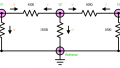
Consider the following circuit that consists of a dependent voltage source I2 having a value of (-2mA) (VR1), a connection link to a resistor R1 that has a value 1K Ohms with a voltage drop of VR1, an independent voltage source V1 having a value of 4 Volts and an independent current source I1 having a value of 1 mAmp as illustrated in Figure 2.
.png)
Figure 2.
Before using Kirchhoff’s Current Law (KCL) at node B, the voltage at node A can be determined using the value of the independent voltage source V1 of 4 Volts:
$$V_{A} = V_{1} = 4 \text{ volts}$$
To determine the KCL at node A, currents need to be identified. Current IA is positive because it enters the node whereas current IB and IC are negative because they leave the node as illustrated in Figure 3.
.png)
Figure 3.
The algebraic sum of all currents at node VA are equal to zero:
$$I_{A} - I_{B} - I_{C} = 0$$
Note that:
$$I_{B} = \frac{V_{B} - V_{A}}{R_{1}}$$
$$I_{C} = I_{1}$$
So that:
$$I_{A} – \frac{V_{B} – V_{A}}{R_{1}} – I_{1} = 0$$
Substitute circuit values:
$$I_{A} – \frac{V_{B} – 4}{1 \text{ k}\Omega} – 1 \text{ mA} = 0$$
Multiply both sides by 1k:
$$[I_{A} – \frac{(V_{B} – 4)}{1 \text{ k}\Omega} – 1 \text{ mA} = 0] (1 \text{ k})$$
Expand:
$$(1 \text{ k})I_{A} – (V_{B} – 4) – 1 = 0$$
$$(1 \text{ k})I_{A} – V_{B} + 4 – 1 = 0$$
Combine terms:
$$(1 \text{ k})I_{A} – V_{B} + 3 = 0$$
Unknowns on left, knowns on right
$$(1 \text{ k})I_{A} – V_{B} = -3$$ [Equation 1]
To determine the KCL at node B, currents need to be identified. Current IA, IB, and IC are positive because they enter the node whereas current IE is negative because it leaves the node as illustrated in Figure 4.
.png)
Figure 4.
The algebraic sum of all currents at node VB are equal to zero:
$$I_{B} + I_{C} + I_{D} - I_{E} = 0$$
Note that:
$$I_{B} = \frac{V_{A}-V_{B}}{R_{1}}$$
$$I_{C} = I_{1}$$
$$I_{D} = I_{2}$$
$$I_{E} = \frac{V_{B}}{R_{2}}
So that:
$$\frac{V_{A} - V_{B}}{R_{1}} + I_{1} + I_{2} - \frac{V_{B}}{R_{2}} = 0$$
Substitute circuit values:
$$\frac{4 - V_{B}}{1 \text{ k}\Omega} + 1 \text{ mA} - (2 \text{ m})V_{R_{1}} - \frac{V_{B}}{2 \text{ k}\Omega} = 0$$
Multiply both sides by 2 k:
$$[\frac{4 - V_{B}}{1 \text{ k}\Omega} + 1 \text{ mA} - (2 \text{ m})V_{R_{1}} - \frac{V_{B}}{2 \text{ k}\Omega} = 0] (2 \text{ k})$$
Expand:
$$2(4 - V_{B}) + 2 - 4V_{R_{1}} - V_{B} = 0$$
$$8 - 2V_{B} + 2 - 4V_{R_{1}} - V_{B} = 0$$
Combine terms:
$$-3V_{B} - 4V_{R_{1}} + 10 = 0$$
Unknowns on left, knowns on right
$$-3V_{B} - 4V_{R_{1}} = -10$$ [Equation 2]
Use Ohm's Law to find ER4:
$$E_{R_{4}} = I_{1}R_{4}$$
Substitute circuit values:
$$E_{R_{4}} = (1 \text{ mA}) (3 \text{ k}\Omega)$$
$$\underline{E_{R_{4}} = 3 \text{ v}}$$
Note that R4 is parallel to R1. That makes ER4 equal to VR1.
$$\underline{V_{R_{1}} = 3 \text{ v}}$$
Use Ohms Law to find IB:
\[ I_{B} = \frac{V_{R1}}{R_{1}} \]
Substitute circuit values:
$$I_{B} = \frac{3 \text{ v}}{1 \text{ k}\Omega}$$
$$\underline{I_{B} = 3 \text{ mA}}$$
Recall currents at node A:
$$I_{A} - I_{B} - I_{C} = 0$$
Solve for IA:
$$I_{A} = I_{B} + I_{C} $$
Substitute circuit values:
$$I_{A} = (3 \text{ mA}) + (1 \text{ mA})$$
$$\underline{I_{A} = 4 \text{ mA}}$$
Note that current ID is current I2:
$$I_{D} = (-2 \text{ m}) (V_{R_{1}})$$
Substitute circuit values:
$$I_{D} = (-2 \text{ m}) (3 \text{ v})$$
$$\underline{I_{D} = - 6 \text{ mA}}$$
Recall currents at node B:
$$I_{B} + I_{C} + I_{D} - I_{E} = 0$$
Solve for IE:
$$I_{E} = I_{B} + I_{C} + I_{D}$$
Substitute circuit values:
$$I_{E} = (3 \text{ mA}) + (1 \text{ mA}) + (-6 \text{ mA})$$
$$\underline{I_{E} = - 2 \text{ mA}}$$
Note that VR1 can be determined from node A and node B:
$$V_{R_{1}} = V_{A} -V_{B}$$
Solve for VB:
$$V_{B} = V_{A} - V_{R_{1}}$$
Substitute circuit values:
$$V_{B} = (4 \text{ v}) - (3 \text{ v})$$
$$\underline{V_{B} = 1 {\text{ v}}}$$
Use the equation associated with the dependent current source to find current I2:
$$I_{2} = (-2 \text{ m}) (V_{R_{1}})$$
Substitute circuit values:
$$I_{2} = (-2 \text{ m}) (3 \text{ v})$$
$$\underline{I_{2} = - 6 \text{ mA}}$$
Use Ohms Law to find the voltage across resistor R3:
$$E_{R_{3}} = (I_{2}) (R_{3})$$
Substitute circuit values:
$$E_{R_{3}} = (-6 \text{ mA}) (4 \text{ k}\Omega)$$
$$\underline{E_{R_{3}} = - 24 \text{ v}}$$
To confirm KVL loop involving the independent voltage source V1 and resistors R1 and R2 the following equation is obtained:
$$V_{1} = E_{R_{1}} + E_{R_{2}}$$
Substitute circuit values and note ER2 equals VB
$$(4 \text{ v}) = (3 \text{ v}) + (1 \text{ v}) $$
Nodal analysis with dependent sources utilized Kirchhoff’s Current Law with Algebra and Ohm’s Law to substitute an unknown voltage for a node and to find other circuit values. By taking the time to carefully label the nodes, by identifying the proper node voltages and polarities, problem solving is made easier and can avoid mistakes.


About the last example with the dependent current source of -2 mA*VR1, I think the mistake is that the voltage at the left side of the current source of 1 mA is taken the same as the voltage on the right side of this source. KCL is not correct for the node VB. I solved this problem with circuit 4 on my TI 89 calculator and this gives a VB of 6 volt instead of the 1 volt and then KCL is OK for node VB.
Greetigs .
Luke.
Remember if Vb is 1 volt then the current in the 2000 ohm resistor is 0.5 mA towards the reference node and not 2 mA from the reference node towards node VB.