 Facebook
 Google
 GitHub
 Linkedin
Design a Luxmeter Using a Light Dependent Resistor
Take a few minutes to characterize a light dependent resistor (LDR) and you can build a simple and reasonably accurate light meter can be built using an LDR and an Arduino.
Introduction
A luxmeter is a device that measures illuminance and luminous emittance using the SI unit of lux. It effectively measures the amount of power from the light falling on a given unit of area, except that the power measurement is weighted to reflect the sensitivity of the human eye to varying wavelengths of light. A simpler way to describe a lux meter is to say that it measures how bright the light falling on the sensor is. Commercially available lux meters vary in price from around $15 up to hundreds of dollars, but it is cheaper and much more fun to build one yourself.
The light sensor for a lux meter can be one of several different types of sensors, including photodiodes and phototransistors, but the easiest to use and often the most readily available type of sensor is a photoresistor or light dependent resistor (LDR). As you would expect, the resistance of an LDR changes as the amount of light falling on it changes. If you can measure the resistance of the LDR and you know the characteristics of your particular LDR, you can quantify the amount of lux falling on the LDR. In general, the brighter the light, the lower the resistance, but unfortunately, the relationship between resistance and lux for an LDR is not a nice linear relationship. It is instead an exponential relationship which is a little trickier to deal with. With a little bit of time though, you can take a few measurements to determine the mathematical relationship between resistance and lux and program the relationship into a microcontroller to create a simple and reasonably effective lux meter.
In this project, I am going to take you through the process of characterizing an LDR, writing software that can calculate illuminance and then building an LDR and Arduino based luxmeter.
Hardware Required
- 1 light dependent resistor (it doesn't matter which one, you don't even need to know the part number)
- 5 kilo ohm resistor
- Arduino
- 2x16 LCD shield
- Breadboard
- Digital Multimeter (DMM)
- Commercial lux meter (for characterizing your LDR)
Characterizing the Light Dependent Resistor
Plug the LDR into the breadboard and ensure that the flat part of the sensor is parallel to the ground.
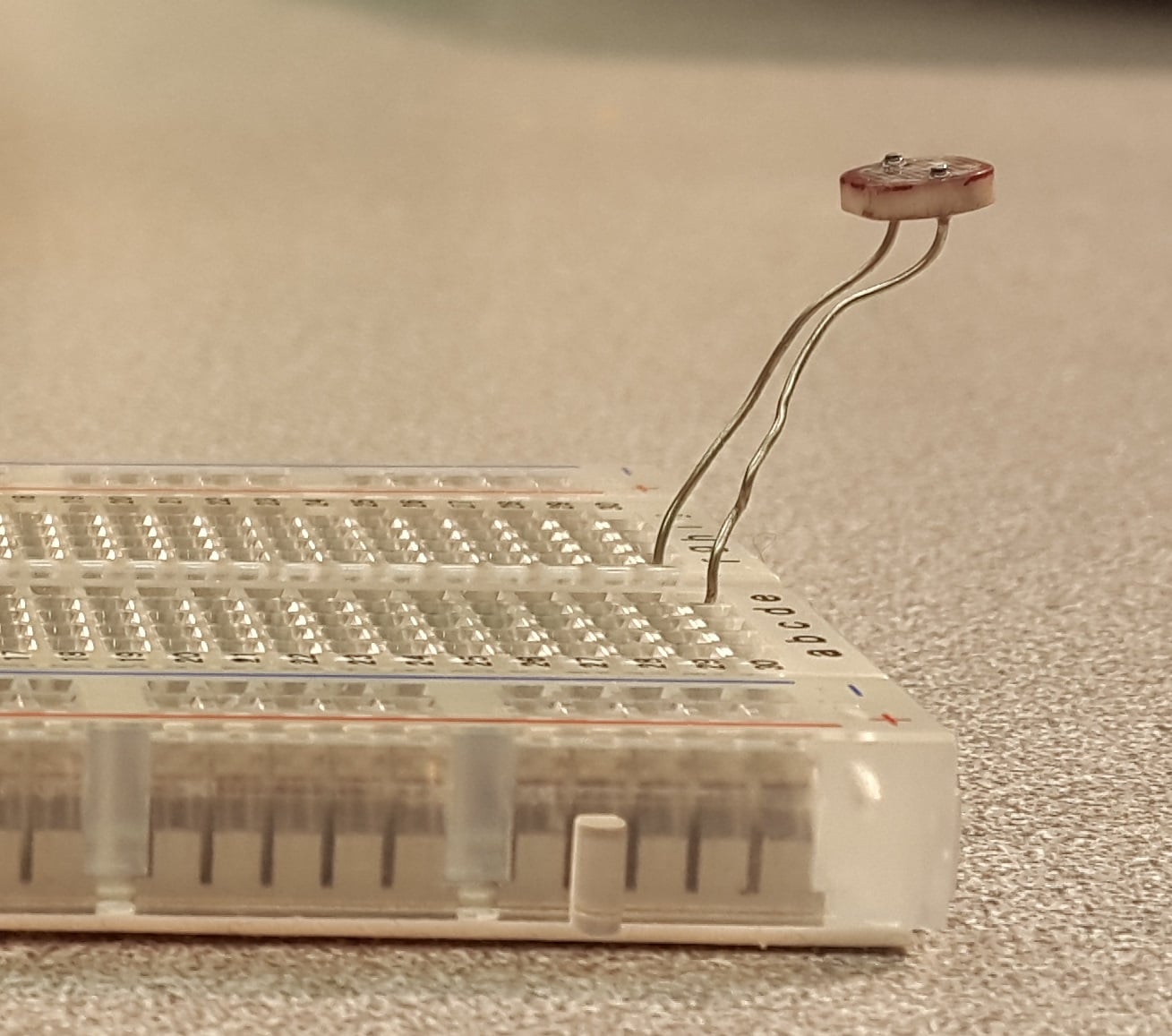
Connect the DMM to the two leads of the LDR and set it to measure resistance. Place the sensor of the commercial light meter beside the LDR.
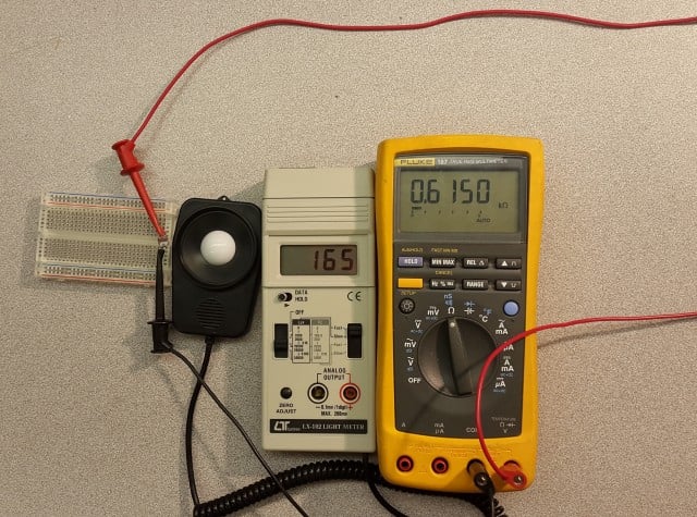
While ensuring that the same levels of light fall on the two sensors, record a reading of the LDR resistance and the light meter lux. Repeat this process for many different lighting levels from very dark (near 0 lux) to very bright (thousands of lux). It is important that at all of these different light levels, you do your best to ensure that both sensors get the same amount of light.
Transfer your readings to a spreadsheet (or enter them directly while you are making measurements) and then make a plot of the illuminance (lux) as a function of resistance. You can download the spreadsheet below which will create the plot and perform all of the necessary analysis from your entries.
Lux_Approximation_from_LDR.xlsx
The measurements that I obtained from my LDR gave me the following plot:
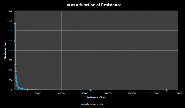
This graph indicates that resistance decreases exponentially as the brightness of the light increases. Ultimately, what we are looking for is the equation for this graph into which we can plug the resistance to obtain the lux. This equation can be obtained directly from the graph, but it can be a little tricky to do this. It is much easier to obtain the equation from a straight line where the form of the equation is \[y=mx+b\] (where m is the slope of the line and b is the y-intercept of the line).
It turns out that if you take the logarithm of both variables (illuminance and resistance) and then re-plot, you will end up with a (more or less) straight line. The base of the logarithm could in theory be anything, but I will use a base-10 log. Here is the resulting plot of log of the lux as a function of the log of the resistance.
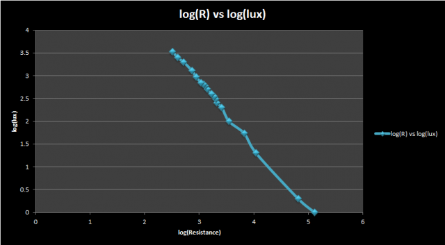
This plot is pretty close to a straight line, and using Excel (although you could also do this by inspection), I obtained a best fit line with a slope of -1.405 and a y-intercept of 7.098 which gives me the equation:
\[log_{10}(lux) = -1.4\times log_{10} \left ( R \right )+7.098\]
This is a good equation for the graph above, but in its current form cannot be used to calculate lux from resistance. I want an equation where \[lux = something\], not \[log(lux) = something\]. Fortunately, with a little bit of algebra, I can manipulate the equation into the form that I want. Let's assume that I start with a general form of the equation above:
\[log_{10}(lux) = m\times log_{10} \left ( R \right )+b\]
Since I used a base-10 logarithm, I can take 10 to the power of each side to get:
\[10^{log_{10}(lux)} = 10^{m \times log_{10}(R)+b}\]
Using some rules of logarithms to simplify both sides of the equation gives:
\[lux = 10^{m \times log_{10}(R)} \times 10^{b}\]
\[= 10^{(log_{10}(R))^{m}} \times 10^{b}\]
\[= R^{m} \times 10^{b}\]
Note that b is a constant, so \[10^{b}\] will also be a constant.
Now using the equation \[lux = 10^{b} \times R^{m}\], you can calculate the illumination on the LDR
For my particular LDR, I end up with the equation
\[lux = (1.25 \times 10^{7}) \times R^{-1.4059}\]
Building the Lux Meter
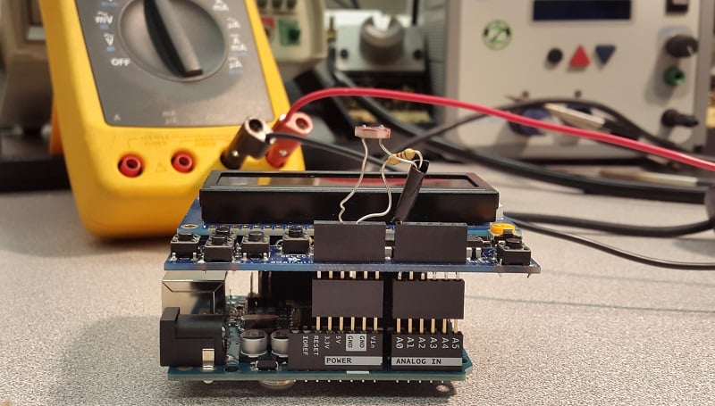
Building the lux meter is very simple. I only need an Arduino, an LCD shield, the LDR that I just characterized and a 5 kohm resistor. In theory, you could use any resistance value, but I chose 5 kohm because the resistance of the LDR was in the order of a few kilo-ohms under typical room lighting conditions. I plugged the shield into the Arduino, and then built a simple voltage divider circuit with the LDR and resistor. This voltage divider circuit is the crux of the sensor circuit. The 5 volt supply is split between the LDR and the 5 kohm resistor. As the resistance of the LDR changes, the fraction of the voltage across the two resistors also changes. If the voltage across the 5 kohm resistor is measured using the Arduino, it is very easy to add some code that will determine what resistance the LDR is exhibiting. The LDR is connected to 5V, the resistor is connected to ground, and the point in between is connected to analog input 0.

This voltage divider circuit can be connected directly to the LCD shield and doesn’t need a breadboard. This picture shows the completed circuit with the LDR and 5 kohm resistor in the LCD shield.
The Light Meter Code
The equation obtained in Part 1 relates the illuminance to the resistance, but the analog input pin of the Arduino only measures voltage, so there are a couple of calculations that have to be done to obtain the resistance.
First the digital representation of the analog voltage must be obtained by using the analogRead function (remember that this is the voltage across the 5 kohm resistor, not the voltage across the LDR)
rawData = analogRead(LDR_PIN);
Second, the digital representation must be converted back into a voltage by scaling the analog-to-digital converter value to the reference voltage:
// MAX_ADC_READING is 1023 and ADC_REF_VOLTAGE is 5<br />
resistorVoltage = (float)ldrRawData / MAX_ADC_READING * ADC_REF_VOLTAGE;
Third, the LDR voltage must be determined. Since 5V is split between the 5 kohm resistor and the LDR, simply subtract the resistor voltage from 5V:
ldrVoltage = ADC_REF_VOLTAGE - resistorVoltage;
Finally, the resistance of the LDR must be calculated based on the voltage (simple resistance calculation for a voltage divider circuit):
ldrResistance = ldrVoltage/resistorVoltage * REF_RESISTANCE; // REF_RESISTANCE is 5 kohm
Once the resistance is obtained, the illuminance (in lux) can be calculated and the value can be output to the LCD.
ldrLux = LUX_CALC_SCALAR * pow(ldrResistance, LUX_CALC_EXPONENT);  <br />
// LUX_CALC_SCALAR and LUX_CALC_EXPONENT are determined by the Excel spreadsheet  <br />
// They are set to 12518931 and -1.405 respectively in my example
The calculations and display output are all done in the loop function and the entire source code for the sketch can be found below. An LCD shield from Adafruit is used to display the lux measurement, so their LCD library must be downloaded for this sketch to work
Putting it All Together
The hardware has been assembled, the code has been written, all that needs to be done is upload the code and compare the results to the commercial light meter. In the video below you can see a side by side comparison of the LDR light meter and an LX-102 light meter from Lutron. At standard room light levels (500 lux and below), the two light meters were within 40 or 50 lux of each other. Under brighter lights, the difference grew to 100 lux or more. This is likely because the characteristic curve I determined experimentally deviates from the actual characteristic curve. If I took more samples and especially focused on getting samples in the range of lighting conditions that I expect to measure, I would probably end up with an equation that more closely represents the actual characteristic curve.
Overall, I would say that the LDR light meter is good enough in a normal room when you just want a ballpark measurement of the lighting levels, but if you want precise and accurate measurements you will need to use a different kind of sensor.
Final Word
-
The LDR luxmeter is not incredibly accurate, but can be good enough in some conditions.
- During LDR characterization, it is very important to ensure the light falling on the LDR and commercial sensor is identical.
- The LDR luxmeter is cheap and easy to make. You only need one commercial light sensor to help you make as many LDR light sensors as you want.
Give this project a try for yourself! Get the BOM.
Related Content


In selecting an LDR, looking at various data sheets it states they vary in sensitivity from green to red. I can’t find one with a chart that says how broad the range is. Do they all cover the blue end as well? I was looking to measure the intensity of LEDs of different color, IR to UV. If diodes are sensitive to light can I use a colored LED as a color sensitive device?
Addition to my previous post. Yes an LED generates a voltage when exposed to light but I can’t tell if the colored lens has a filtering effect. My yellow LED generates about 1.3 V when exposed to a white or blue LED but less when exposed to a red LED. Was it a dimmer red LED or was it the color?