 Facebook
 Google
 GitHub
 Linkedin
DC Electric Circuits
Voltmeter Design
18 questions By Tony R. Kuphaldt
-
Question 1 of 18
Suppose I were about to measure an unknown voltage with a manual-range voltmeter. This particular voltmeter has several different voltage measurement ranges to choose from:
- 500 volts
- 250 volts
- 100 volts
- 50 volts
- 25 volts
- 10 volts
- 5 volts
What range would be best to begin with, when first measuring this unknown voltage with the meter? Explain your answer.
Reveal answerBegin by setting the voltmeter to its highest range: 500 volts. Then, see if the movement needle registers anything with the meter leads connected to the circuit. Decide to change the meter’s range based on this first indication.
Notes:I always like to have my students begin their test equipment familiarity by using old-fashioned analog multimeters. Only after they have learned to be proficient with an inexpensive meter do I allow them to use anything better (digital, auto-ranging) in their work. This forces students to appreciate what a “fancy” meter does for them, as well as teach them basic principles of instrument ranging and measurement precision.
-
Question 2 of 18
What would happen to this meter movement, if connected directly to a 6-volt battery?

Reveal answerTwo things would happen: first, the movement would most likely be damaged from excessive current. Secondly, the needle would move to the left instead of the right (as it normally should), because the polarity is backward.
Notes:When an electromechanical meter movement is overpowered, causing the needle to “slam” all the way to one extreme end of motion, it is commonly referred to as “pegging” the meter. I’ve seen meter movements that have been “pegged” so badly that the needles are bent from hitting the stop!
Based on your students knowledge of meter movement design, ask them to tell you what they think might become damaged in a severe over-power incident such as this. Tell them to be specific in their answers.
-
Question 3 of 18
An important step in building any analog voltmeter or ammeter is to accurately determine the coil resistance of the meter movement. In electrical metrology, it is often easier to obtain extremely precise (“standard”) resistance values than it is to obtain equally precise voltage or current measurements. One technique that may be used to determine the coil resistance of a meter movement without need to accurately measure voltage or current is as follows.
First, connect a decade box type of variable resistance in series with a regulated DC power supply, then to the meter movement to be tested. Adjust the decade box’s resistance so that the meter movement moves to some precise point on its scale, preferably the full-scale (100%) mark. Record the decade box’s resistance setting as R1:
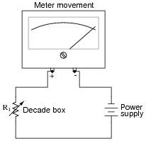
Then, connect a known resistance in parallel with the meter movement’s terminals. This resistance will be known as Rs, the shunt resistance. The meter movement deflection will decrease when you do this. Re-adjust the decade box’s resistance until the meter movement deflection returns to its former place. Record the decade box’s resistance setting as R2:

The meter movement’s coil resistance (Rcoil) may be calculated following this formula:
Rcoil = Rs R2(R1 − R2) Your task is to show where this formula comes from, deriving it from Ohm’s Law and whatever other equations you may be familiar with for circuit analysis.
Hint: in both cases (decade box set to R1 and set to R2), the voltage across the meter movement’s coil resistance is the same, the current through the meter movement is the same, and the power supply voltage is the same.
Reveal answerOne place to start from is the voltage divider equation, VR = VT R/(RT) applied to each circuit scenario:
Vmeter = Rcoil R1 RcoilVmeter = Rcoil || Rs R2 (Rcoil || Rs)Since we know that the meter’s voltage is the same in the two scenarios, we may set these equations equal to each other:
Rcoil R1 Rcoil= Rcoil || Rs R2 (Rcoil || Rs)Note: the double-bars in the above equation represent the parallel equivalent of Rcoil and Rs, for which you will have the substitute the appropriate mathematical expression.
Notes:This problem is really nothing more than an exercise in algebra, although it also serves to show how precision electrical measurements may be obtained by using standard resistors rather than precise voltmeters or ammeters.


The equations in the answer to question 3 are incorrect. The first two equations are missing Vt on the right side. Also, all of the equations are missing plus signs in the denominators.