Facebook
 Google
 GitHub
 Linkedin
Avoid Rework and Production Delays by Aligning Electrical and Mechanical Design
Learn how to prevent costly assembly delays by synchronizing ECAD and MCAD workflows through continuous 3D validation. This also stabilizes production and eliminates mid-cycle re-spins.
Design-induced issues account for roughly 70% of all rework in engineering and construction projects, highlighting how design errors and coordination failures drive rework more than fabrication problems.
Modern electronic products function as unified electromechanical systems rather than independent components. PCB layout, enclosure geometry, mounting strategy, connector placement, structural supports, and thermal management are physically linked, and changes in one domain affect the others.
Yet electrical and mechanical development often progress in parallel with limited cross-domain validation. Each discipline optimizes within its own priorities, assuming integration will converge later. This accelerates early progress but defers risk.
Small shifts in board outlines, connector locations, or mounting features accumulate until the first physical build exposes misalignment and interference.
When conflicts surface during prototyping or pilot production, they are often attributed to manufacturing. In most cases, fabrication performs as specified. The root cause is the interaction of independently optimized subsystems that were never formally validated as a unified assembly. Rework is rarely the result of fabrication errors and is more often caused by integration assumptions that were never formally validated.
The Integration Gap in Modern Product Development
Electrical and mechanical systems are inherently interdependent, yet development workflows often treat them as loosely coupled until late in the design cycle. When cross-domain constraints are not validated continuously, small, independent decisions accumulate into integration risk that surfaces only during physical assembly.
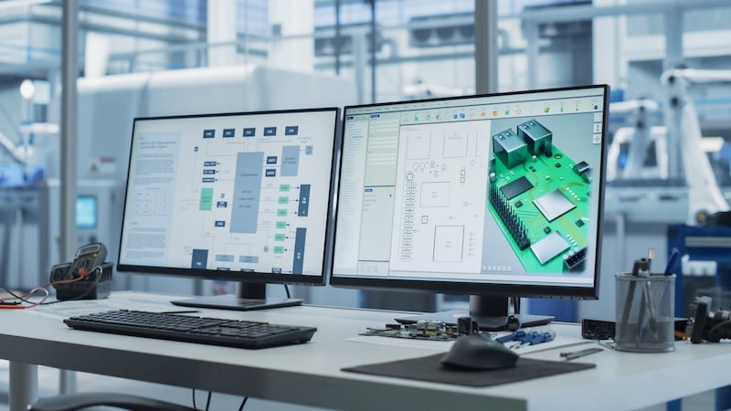
Complex assemblies depend on precise interface alignment. Uncoordinated design turns these interfaces into failure points. Image used courtesy of Adobe Stock
In many organizations, electrical and mechanical engineering operate as adjacent but structurally separate functions. This separation is not necessarily problematic in itself. The issue arises when system-level integration is treated as a downstream activity rather than a concurrent constraint.
Common structural realities include:
- Separate teams with different reporting lines
- Distinct toolchains such as ECAD and MCAD platforms
- File exchanges through neutral formats rather than live model synchronization
- Independent documentation standards and revision controls
Each discipline optimizes for its own performance metrics.
Electrical engineering priorities typically include:
- Signal integrity and controlled impedance routing
- Routing density and layer stack efficiency
- EMI mitigation and grounding strategies
- Component placement for electrical performance
Mechanical engineering priorities typically include:
- Structural rigidity and vibration resistance
- Manufacturability of housings and supports
- Thermal dissipation through material and airflow strategy
- Assembly and serviceability constraints
Both sets of priorities are valid. The integration gap emerges when these optimization paths are not reconciled through structured interface ownership.
Organizational separation and optimization priorities
| Dimension | Electrical Engineering Focus | Mechanical Engineering Focus | Integration Risk When Unaligned |
| Organizational Structure | Separate team ownership | Separate team ownership | Interfaces lack formal cross-domain governance |
| Tool Environment | ECAD platforms | MCAD platforms | Model drift between unsynchronized systems |
| File Exchange | STEP exports, static board models | Imported geometry snapshots | Outdated reference geometry persists |
| Revision Control | PCB revision cycles | Enclosure/tooling revision cycles | Asynchronous updates cause misalignment |
| Primary Optimization | Signal integrity, routing density, EMI control | Structural rigidity, manufacturability, thermal management | Local optimization reduces global system compatibility |
| Mounting Strategy | Hole placement for layout efficiency | Standoff geometry and enclosure constraints | Positional tolerance stack-up conflicts |
| Connector Placement | Electrical grouping and routing efficiency | Panel cutout alignment and accessibility | Envelope and alignment mismatch |
| Thermal Strategy | Component heat dissipation | Airflow paths and enclosure heat transfer | Airflow obstruction or localized overheating |
| Assembly Consideration | Component spacing on the board | Fastener access and structural sequencing | Tool access and installation conflicts |
Studies show that up to 70 percent of rework in engineering and construction projects is driven by design-related issues, highlighting that coordination failures and design decisions, not fabrication quality, are often the primary cause of costly rework.
When integration discipline is deferred, validation occurs only after fabrication or tooling commitments have been made. Interface conflicts then surface during prototype assembly or early production, where correction requires PCB re-spins, enclosure modification, or schedule compression. The issue is not technical capability, but workflow structure.
When cross-domain constraints are not treated as first-class engineering parameters, risk is discovered downstream, where correction costs are significantly higher.
Where Coordination Breaks Down in Practice
Integration failures appear at predictable mechanical–electrical interface points. They are rarely fabrication errors. They are the result of independently optimized features that were never validated as a unified system.

Electrical precision in PCB design must align with mechanical constraints to ensure successful system integration. Image used courtesy of Adobe Stock
In the following subsections, we highlight common causes of mechanical-electrical design errors.
PCB-to-Enclosure Misalignment
One of the most common failure modes is dimensional drift between the PCB and enclosure. Typical causes include:
- Mounting hole relocation during layout iteration
- Standoff height variation combined with PCB thickness tolerance
- Late-stage board outline changes
- Fastener access obstructed by component height
When positional tolerances are allocated independently across ECAD and MCAD, cumulative stack-up can exceed alignment margins. Datum reference inconsistency between board origin and enclosure reference surfaces further compounds the issue.
Under worst-case conditions, the system depends on a forced fit rather than controlled geometry.
Connector Placement Conflicts
Connectors must simultaneously satisfy electrical, mechanical, and user constraints. Misalignment typically occurs when PCB placement shifts without synchronized enclosure updates. Common outcomes include:
- Panel cutout misalignment
- Cable bend radius violations
- Strain relief interference
- Mechanical stress is transferred to the solder joints
These issues often stem from incomplete envelope modeling and a lack of early 3D co-validation between board and housing geometry.
Thermal and Structural Interference
Thermal and structural analyses are frequently performed within domain boundaries but not reconciled at the system level. Examples include:
- Heat sinks are sized correctly, but airflow is restricted by enclosure features
- Board deflection under mounting torque affects solder joint reliability
- Thermal expansion mismatch between housing and PCB mounting points
When thermal simulation and structural modeling are not validated against the final enclosure geometry and board layout simultaneously, reliability risks remain latent.
Assembly Access Constraints
Assembly conflicts often reveal integration breakdown that digital reviews missed. Typical problems include:
- Tool access blocked by component proximity
- Inaccessible fasteners
- Installation sequence conflicts
- Designs that function geometrically but cannot scale to automated assembly
Assembly feasibility must be validated as a design constraint, not discovered during build.
Coordination breakdown is not random. It occurs at repeatable interface boundaries where cross-domain constraints were never formally governed. When these interfaces are validated late, correction requires rework, tooling modification, and schedule compression.
Why Traditional Review Processes Miss These Issues
Traditional design reviews often focus on component performance rather than system behavior under real operating conditions. As a result, integration risks between mechanical, electrical, and control systems frequently remain hidden until late-stage testing or deployment.
Late-Stage Design Reviews
In many workflows, integration validation occurs near the end of the design cycle, when geometry is largely fixed, and tooling decisions are underway. Reviews often focus on nominal fit and discipline-specific drawings rather than cross-domain tolerance interaction. As a result, worst-case stack-ups and cumulative variation effects remain untested until physical assembly exposes them.
Siloed CAD Environments
ECAD and MCAD systems frequently operate in parallel without structured synchronization. Static model exports and manual updates introduce dimensional drift between board and enclosure geometry. Without disciplined cross-domain version control, digital models gradually diverge from actual design intent across disciplines.
Component Optimization Over System Validation
Electrical and mechanical teams are typically measured by domain performance, not interface stability. Each discipline can achieve local optimization while system alignment degrades incrementally. When no one owns cross-domain boundaries explicitly, integration becomes secondary to internal efficiency.
Review Timing Misalignment
Design reviews are often triggered by milestone deadlines rather than interface changes. Small geometry shifts between formal reviews accumulate without revalidation. By the time the system is examined holistically, misalignment may already exceed acceptable margins.
Consequence: Issues Surface Downstream
When integration discipline is deferred, failures emerge during prototype assembly, first article inspection, or pilot production. At that stage, correction requires PCB re-spins, tooling modification, and schedule compression. What appears to be a manufacturing setback is often a predictable outcome of unmanaged interface governance.
Structural Correctives That Reduce Rework
Reducing rework requires structural integration discipline embedded early in development. This is typically achieved through integrated mechanical and electrical engineering support, where cross-domain constraints are validated before design divergence occurs.

Automation does not create precision. It exposes whether the product was engineered for it. Image used courtesy of Adobe Stock
Early Interface Definition
Mechanical–electrical boundaries must be defined at the concept stage. Connector envelopes, mounting strategy, and shared datum references should be stabilized early so geometry evolves within controlled constraints rather than drifting independently.
Cross-Domain Tolerance Planning
Tolerance allocation must be treated as a system-level budget. PCB variation, enclosure manufacturing tolerance, and hardware clearance must be evaluated cumulatively under worst-case conditions before tooling release.
Integrated 3D Co-Validation
Continuous ECAD–MCAD synchronization is essential. Board geometry, enclosure features, connector alignment, and mounting interfaces should be validated in 3D throughout iteration, not only at formal review gates.
Assembly and Serviceability Modeling
Assembly feasibility must be engineered into the design. Tool access, installation sequence, and service constraints should be validated digitally before prototype build.
Pre-Production Manufacturability Gate
Before committing to tooling, cross-disciplinary validation must confirm interface stability, assembly feasibility, and process readiness. Production readiness should be verified at the system level, not assumed from discipline-level completion.
Overview of practical considerations and risk as a function of structural weaknesses
| Structural Weakness | What Happens in Practice | Resulting Risk |
| Late-Stage Design Reviews | Integration checks occur after geometry, tooling, and board layouts are already largely fixed. Reviews emphasize nominal fit rather than worst-case variation. | Hidden tolerance conflicts emerge during assembly or prototype validation. |
| Siloed CAD Environments | ECAD and MCAD models evolve separately through static exports and manual updates. Synchronization between disciplines is inconsistent. | Board and enclosure geometry gradually diverge, leading to alignment errors. |
| Component Optimization Over System Validation | Teams optimize electrical and mechanical performance within their own domains without formal ownership of cross-domain interfaces. | Local improvements create incremental system misalignment that remains unnoticed until integration. |
| Review Timing Misalignment | Design reviews are triggered by schedule milestones instead of interface changes. Small geometry shifts accumulate between reviews. | Integration problems compound silently until late validation stages. |
| Downstream Discovery of Issues | Interface conflicts appear during prototype assembly, first article inspection, or pilot production. | Corrections require PCB re-spins, tooling changes, and compressed schedules. |
Execution Lessons from Multidisciplinary Product Development
Across electromechanical programs, integration failures follow consistent patterns.
Most failures originate from unvalidated assumptions at shared interfaces. Parallel development is not inherently flawed, but unmanaged boundaries accumulate risk. Early 3D validation significantly reduces revision cycles, while cross-domain tolerance modeling prevents cumulative misalignment. When tooling investment precedes structured interface validation, correction costs escalate rapidly.
Effective integration is not a software feature. It is a governance discipline. Teams that formalize mechanical–electrical interface ownership and synchronized validation consistently reduce PCB re-spins and enclosure modifications. This also minimizes schedule compression and cost escalation.
Electromechanical systems fail predictably at unmanaged interfaces. When coordination is embedded as a primary engineering constraint, rework decreases, and production timelines stabilize.
Key Takeaways
Production delays often blamed on manufacturing are frequently rooted in early coordination gaps between electrical and mechanical design. When PCB layout, enclosure geometry, mounting strategy, and thermal constraints evolve without synchronized validation, integration risk accumulates and surfaces during physical builds.
The solution is not more review meetings. It is a structured integration discipline embedded from the start.
Modern electromechanical development requires synchronized ECAD–MCAD validation, cross-domain tolerance planning, shared datum strategies, and explicit interface ownership.
When coordination becomes a primary engineering constraint, misalignment is resolved digitally rather than physically. PCB re-spins decline, enclosure modifications decrease, and production timelines stabilize through disciplined control of system interfaces. For teams looking to reduce rework and stabilize production, working with a production-ready engineering partner ensures integration is validated before manufacturing begins.