Facebook
 Google
 GitHub
 Linkedin
Intro Lab - A Simple Lighting Circuit
Project Overview
In this project, you will build the simplest complete circuit in this collection of experiments: a battery and an incandescent lamp, as illustrated in Figure 1.
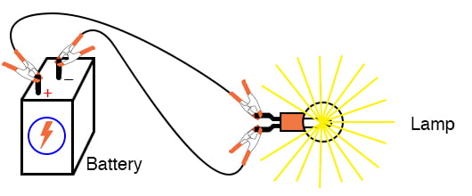
Figure 1. Powering a light with a battery.
We will be able to learn several important circuit concepts from this circuit. When you are done, save the setup because you can also use it for the nonlinear resistance project.
Parts and Materials
- 6 V battery
- 6 V incandescent lamp
- Jumper wires
- Breadboard
- Terminal strip
Learning Objectives
- The essential configuration needed to make a circuit
- Normal voltage drops in an operating circuit
- Importance of continuity to a circuit
- Working definitions of open and short circuits
- Breadboard usage
- Terminal strip usage
Instructions
Step 1: Connect the lamp to the battery, as shown in the illustration of Figure 1 and the schematic diagram of Figure 2.
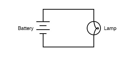
Figure 2. Schematic diagram of a lamp connected to a battery.
The lamp should light, assuming the battery and lamp are both in good condition, and they are matched to one another in terms of voltage.
The Effects of an Open Circuit
Step 2: If there is a break (also referred to as an open circuit or a discontinuity) anywhere in the circuit, the lamp will fail to light, and it does not matter where such a break occurs. Figures 3 through 6 illustrate four different places where a break could occur in this simple circuit and prevent the lamp from lighting.
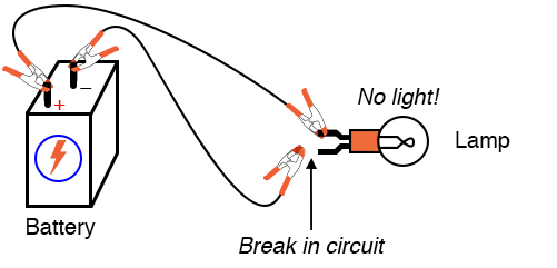
Figure 3. Break in the circuit at a lamp terminal.
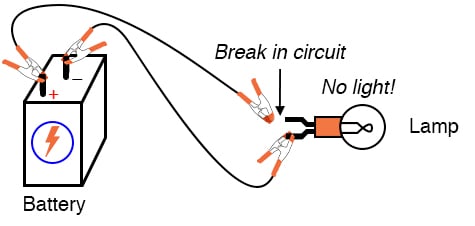
Figure 4. Break in the circuit at the other lamp terminal.
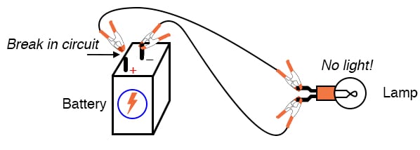
Figure 5. Break in the circuit at the positive battery terminal.
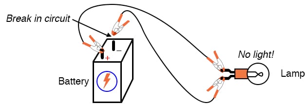
Figure 6. Break in the circuit at the negative battery terminal.
Try breaking the circuit at these locations to confirm for yourself that the lamp will not light with any break in the circuit.
Many students assume that because electrons leave the negative (-) side of the battery and continue through the circuit to the positive (+) side. Also that the wire connecting the negative terminal of the battery to the lamp is more important to circuit operation than the other wire providing a return path for electrons back to the battery. This is not true!
Step 3: Using your multimeter set to the appropriate DC volt range, measure the voltage across the battery, across the lamp, and across each jumper wire. Familiarize yourself with the normal voltages in a functioning circuit.
Step 4: Now, break the circuit at one point and re-measure the voltage between the same sets of points from Step 3. Also, measure the voltage across the break, as shown in Figure 7.
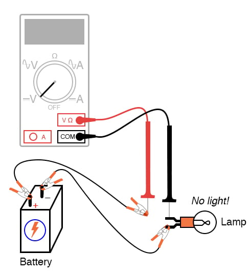
Figure 7. Measure the voltage across the break in the circuit.
What voltages measure the same as before? What voltages have been different since introducing the break? How much voltage is manifested or dropped across the break? What is the polarity of the voltage drop across the break, as indicated by the meter?
Step 5: Re-connect the jumper wire to the lamp, and break the circuit in another place. Measure all voltage drops again, familiarizing yourself with the voltages of an open circuit.
Step 6: Construct the same circuit on a breadboard, taking care to place the lamp and wires into the breadboard in such a way that continuity will be maintained (Figure 8).
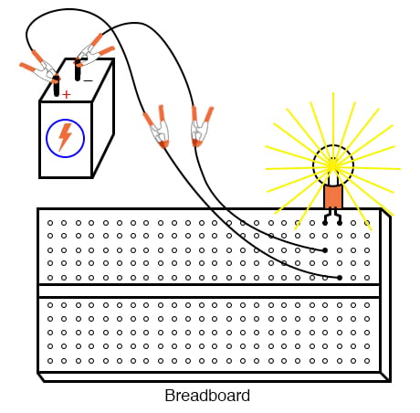
Figure 8. Breadboard implementation of the simple lamp circuit.
The example shown here is only that: an example, not the only way to build this circuit on a breadboard.
Step 7: Experiment with different configurations on the breadboard, plugging the lamp into different holes.
The Effects of a Short Circuit
If you encounter a situation where the lamp refuses to light up, and the connecting wires are getting warm, you probably have a situation known as a short circuit, where a lower-resistance path than the lamp bypasses current around the lamp, preventing enough voltage from being dropped across the lamp to light it up. Figure 9 is is an example of a short circuit made on a breadboard.
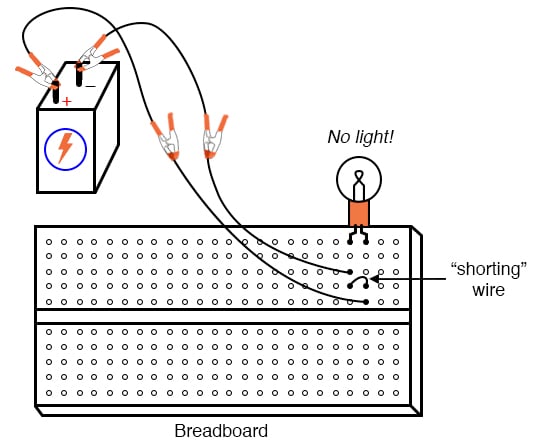
Figure 9. Example of a short circuit in the simple lamp circuit.
Figure 10 is an example of an accidental short circuit of the type typically made by students unfamiliar with breadboard usage.
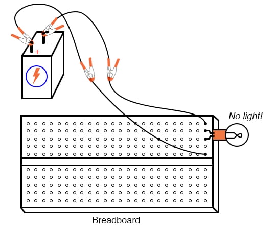
Figure 10. Example of an accidental short circuit on a breadboard.
Here there is no shorting wire present on the breadboard, yet there is a short circuit, and the lamp refuses to light. Based on your understanding of breadboard hole connections, can you determine where the short is in this circuit?
Tips to Avoid Short Circuits
Short circuits are generally to be avoided, as they result in very high current flow rates, which cause wires to heat up and battery power sources to deplete. If the power source is substantial enough, a short circuit may also cause heat of explosive proportions to manifest, thus creating equipment damage and hazard to nearby personnel. This is what happens when a tree limb shorts across wires on a power line; the limb—being composed of wet wood—acts as a low-resistance path to electric current, resulting in heat and sparks.
Step 9: You may also build the battery/lamp circuit on a terminal strip, as illustrated in Figure 11.
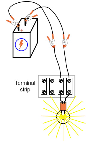
Figure 11. Terminal strip implementation of the simple lamp circuit
The terminal strip is a length of insulating material with metal bars and screws to attach wires and component terminals.
Related Content
Learn more about the fundamentals behind this project in the resources below.
Textbook:
Worksheets: