Facebook
 Google
 GitHub
 Linkedin
AC Voltmeters and Ammeters
AC electromechanical meter movements come in two basic arrangements: those based on DC movement designs, and those engineered specifically for AC use.
Permanent-magnet moving coil (PMMC) meter movements will not work correctly if directly connected to alternating current, because the direction of needle movement will change with each half-cycle of the AC. (Figure below)
Permanent-magnet meter movements, like permanent-magnet motors, are devices whose motion depends on the polarity of the applied voltage (or, you can think of it in terms of the direction of the current).
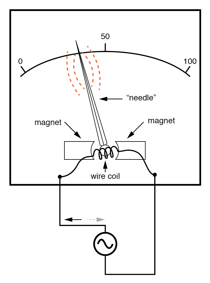
Passing AC through this D’Arsonval meter movement causes useless flutter of the needle.
In order to use a DC-style meter movement such as the D’Arsonval design, the alternating current must be rectified into DC.
This is most easily accomplished through the use of devices called diodes. We saw diodes used in an example circuit demonstrating the creation of harmonic frequencies from a distorted (or rectified) sine wave. Without going into elaborate detail over how and why diodes work as they do, just remember that they each act like a one-way valve for current to flow.
The arrowhead in each diode symbol points in the permitted direction of current flow.
Arranged in a bridge, four diodes will serve to steer AC through the meter movement in a constant direction throughout all portions of the AC cycle:
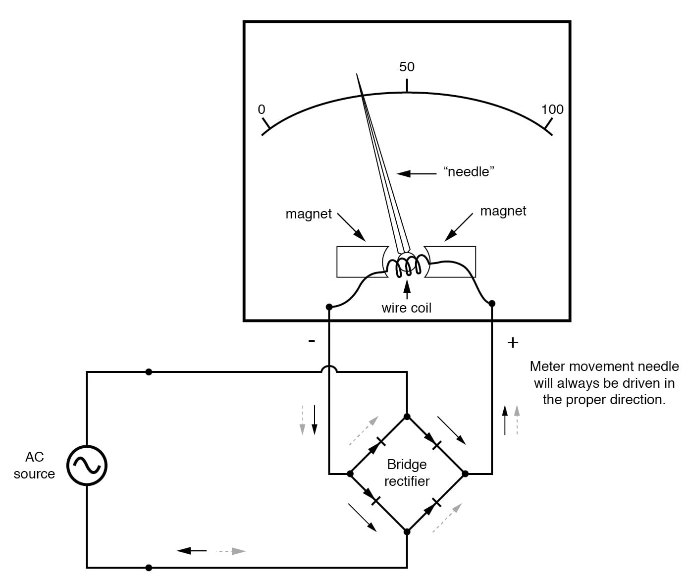
Passing AC through this Rectified AC meter movement will drive it in one direction.
Another strategy for a practical AC meter movement is to redesign the movement without the inherent polarity sensitivity of the DC types.
This means avoiding the use of permanent magnets. Probably the simplest design is to use a nonmagnetized iron vane to move the needle against spring tension, the vane being attracted toward a stationary coil of wire energized by the AC quantity to be measured as in the figure below.
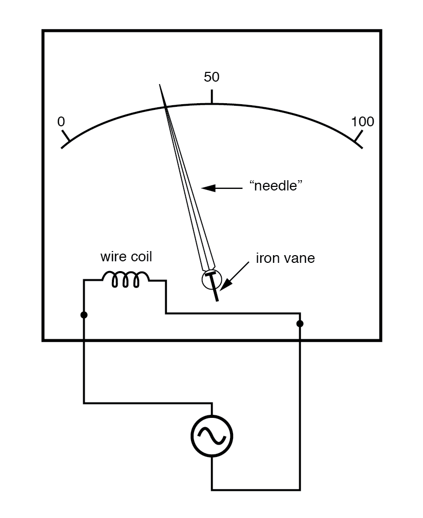
Iron-vane electromechanical meter movement.
Electrostatic attraction between two metal plates separated by an air gap is an alternative mechanism for generating a needle-moving force proportional to applied voltage.
This works just as well for AC as it does for DC, or should I say, just as poorly! The forces involved are very small, much smaller than the magnetic attraction between an energized coil and an iron vane, and as such these “electrostatic” meter movements tend to be fragile and easily disturbed by physical movement.
But, for some high-voltage AC applications, the electrostatic movement is an elegant technology.
If nothing else, this technology possesses the advantage of extremely high input impedance, meaning that no current need be drawn from the circuit under test. Also, electrostatic meter movements are capable of measuring very high voltages without need for range resistors or other, external apparatus.
When a sensitive meter movement needs to be re-ranged to function as an AC voltmeter, series-connected “multiplier” resistors and/or resistive voltage dividers may be employed just as in DC meter design: (Figure below)
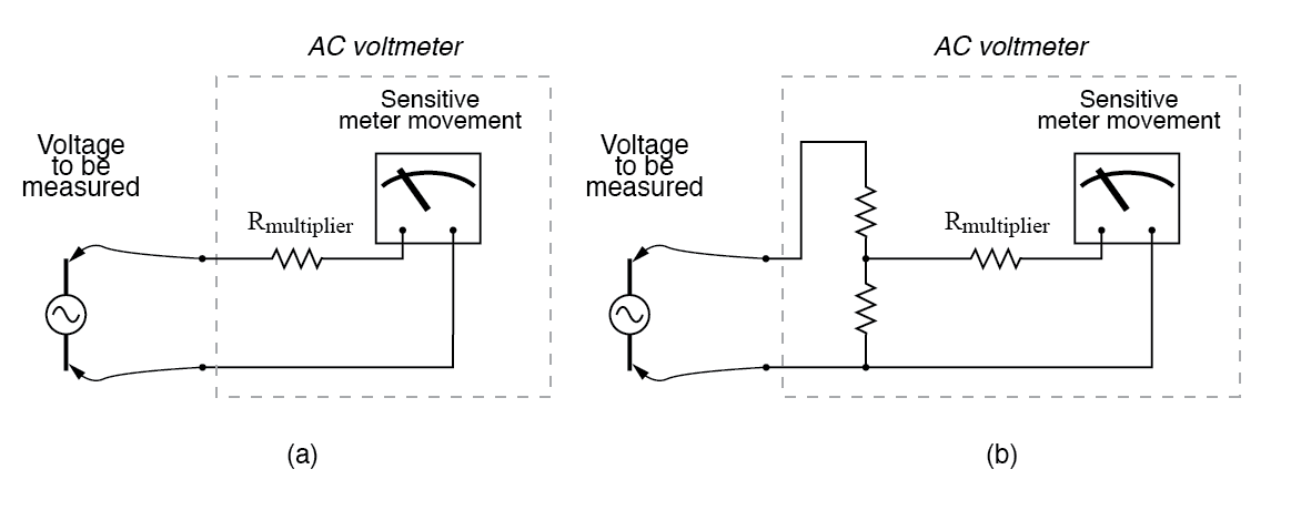
Multiplier resistor (a) or resistive divider (b) scales the range of the basic meter movement.
Capacitors may be used instead of resistors, though, to make voltmeter divider circuits. This strategy has the advantage of being non-dissipative (no true power consumed and no heat produced):
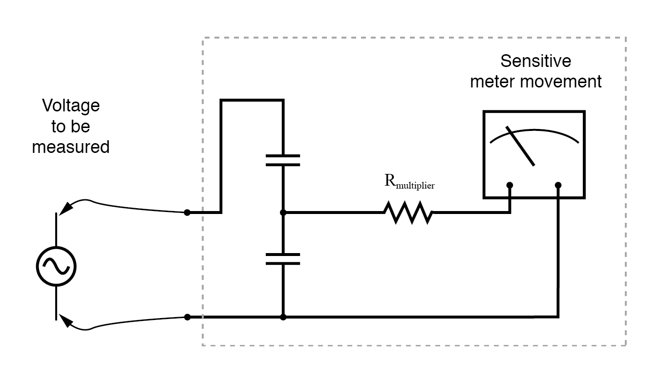
AC voltmeter with capacitive divider.
If the meter movement is electrostatic, and thus inherently capacitive in nature, a single “multiplier” capacitor may be connected in series to give it a greater voltage measuring range, just as a series-connected multiplier resistor gives a moving-coil (inherently resistive) meter movement a greater voltage range:
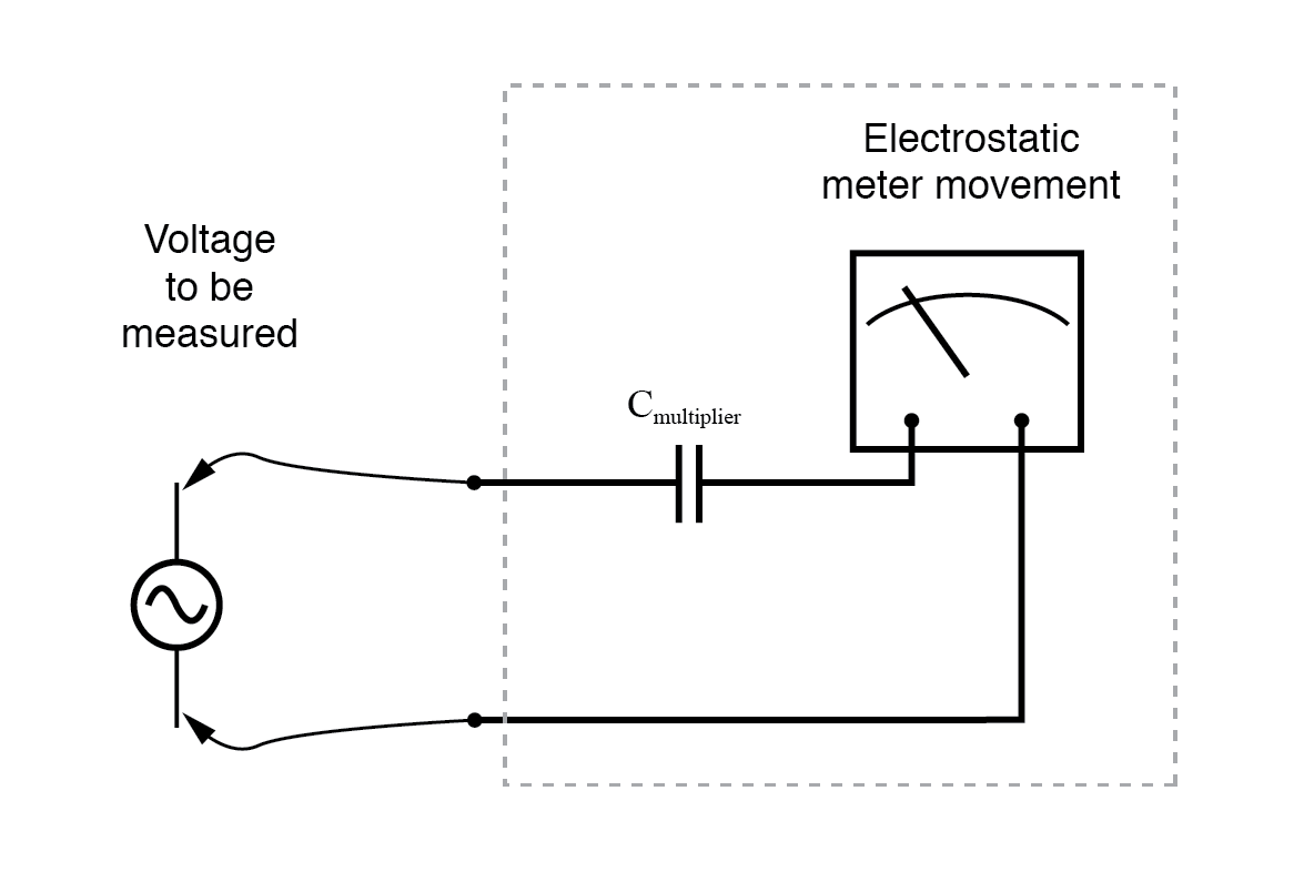
An electrostatic meter movement may use a capacitive multiplier to multiply the scale of the basic meter movement.
The Cathode Ray Tube (CRT) mentioned in the DC metering chapter is ideally suited for measuring AC voltages, especially if the electron beam is swept side-to-side across the screen of the tube while the measured AC voltage drives the beam up and down.
A graphical representation of the AC wave shape and not just a measurement of magnitude can easily be had with such a device. However, CRT’s have the disadvantages of weight, size, significant power consumption, and fragility (being made of evacuated glass) working against them.
For these reasons, electromechanical AC meter movements still have a place in practical usage.
With some of the advantages and disadvantages of these meter movement technologies having been discussed already, there is another factor crucially important for the designer and user of AC metering instruments to be aware of. This is the issue of RMS measurement.
As we already know, AC measurements are often cast in a scale of DC power equivalence, called RMS (Root-Mean-Square) for the sake of meaningful comparisons with DC and with other AC waveforms of varying shape. None of the meter movement technologies so far discussed inherently measure the RMS value of an AC quantity.
Meter movements relying on the motion of a mechanical needle (“rectified” D’Arsonval, iron-vane, and electrostatic) all tend to mechanically average the instantaneous values into an overall average value for the waveform.
This average value is not necessarily the same as RMS, although many times it is mistaken as such. Average and RMS values rate against each other as such for these three common waveform shapes:
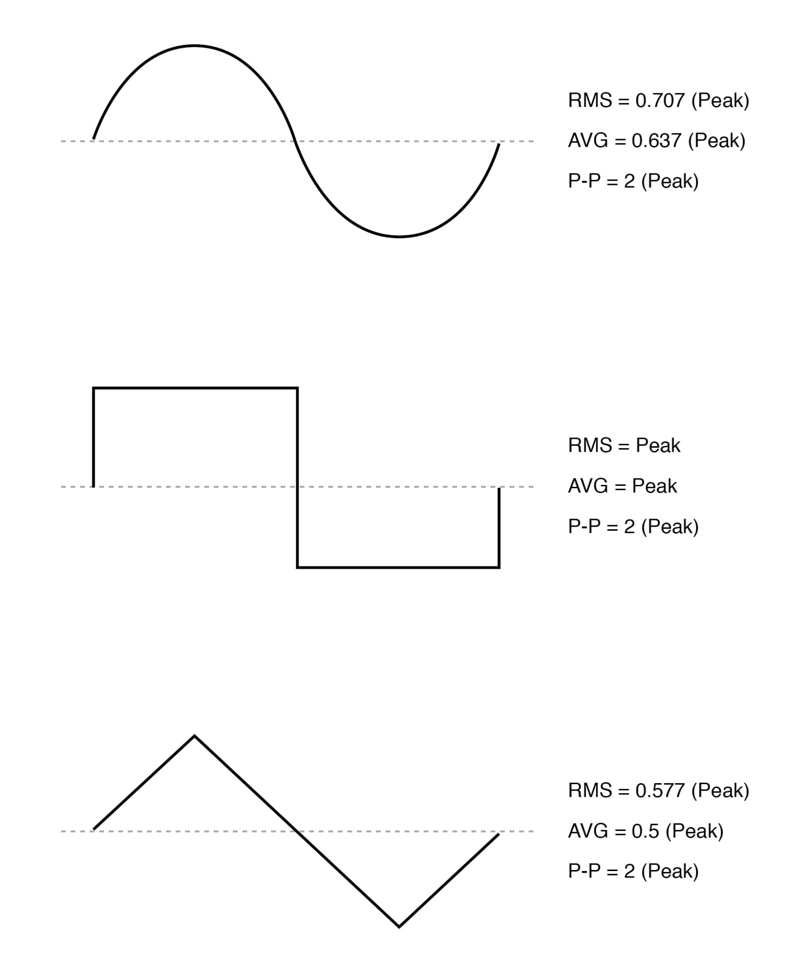
RMS, Average, and Peak-to-Peak values for sine, square, and triangle waves.
Since RMS seems to be the kind of measurement most people are interested in obtaining with an instrument, and electromechanical meter movements naturally deliver average measurements rather than RMS, what are AC meter designers to do? Cheat, of course!
Typically the assumption is made that the waveform shape to be measured is going to be sine (by far the most common, especially for power systems), and then the meter movement scale is altered by the appropriate multiplication factor.
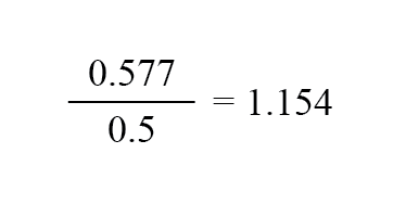
For sine waves we see that RMS is equal to 0.707 times the peak value while Average is 0.637 times the peak, so we can divide one figure by the other to obtain an average-to-RMS conversion factor of 1.109:

In other words, the meter movement will be calibrated to indicate approximately 1.11 times higher than it would ordinarily (naturally) indicate with no special accommodations. It must be stressed that this “cheat” only works well when the meter is used to measure pure sine wave sources.
Note that for triangle waves, the ratio between RMS and Average is not the same as for sine waves:
With square waves, the RMS and Average values are identical! An AC meter calibrated to accurately read RMS voltage or current on a pure sine wave will not give the proper value while indicating the magnitude of anything other than a perfect sine wave.
This includes triangle waves, square waves, or any kind of distorted sine wave. With harmonics becoming an ever-present phenomenon in large AC power systems, this matter of accurate RMS measurement is no small matter.
The astute reader will note that I have omitted the CRT “movement” from the RMS/Average discussion. This is because a CRT with its practically weightless electron beam “movement” displays the Peak (or Peak-to-Peak if you wish) of an AC waveform rather than Average or RMS.
Still, a similar problem arises: how do you determine the RMS value of a waveform from it? Conversion factors between Peak and RMS only hold so long as the waveform falls neatly into a known category of shape (sine, triangle, and square are the only examples with Peak/RMS/Average conversion factors given here!).
One answer is to design the meter movement around the very definition of RMS: the effective heating value of an AC voltage/current as it powers a resistive load. Suppose that the AC source to be measured is connected across a resistor of known value, and the heat output of that resistor is measured with a device like a thermocouple.
This would provide a far more direct measurement means of RMS than any conversion factor could, for it will work with ANY waveform shape whatsoever:
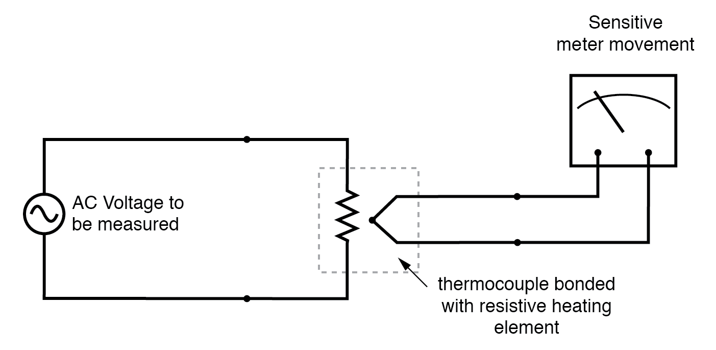
Direct reading thermal RMS voltmeter accommodates any wave shape.
While the device shown above is somewhat crude and would suffer from unique engineering problems of its own, the concept illustrated is very sound. The resistor converts the AC voltage or current quantity into a thermal (heat) quantity, effectively squaring the values in real-time.
The system’s mass works to average these values by the principle of thermal inertia, and then the meter scale itself is calibrated to give an indication based on the square-root of the thermal measurement: perfect Root-Mean-Square indication all in one device!
In fact, one major instrument manufacturer has implemented this technique into its high-end line of handheld electronic multimeters for “true-RMS” capability.
Calibrating AC voltmeters and ammeters for different full-scale ranges of operation is much the same as with DC instruments: series “multiplier” resistors are used to give voltmeter movements higher range, and parallel “shunt” resistors are used to allow ammeter movements to measure currents beyond their natural range.
However, we are not limited to these techniques as we were with DC: because we can use transformers with AC, meter ranges can be electromagnetically rather than resistively “stepped up” or “stepped down,” sometimes far beyond what resistors would have practically allowed for.
Potential Transformers (PT’s) and Current Transformers (CT’s) are precision instrument devices manufactured to produce very precise ratios of transformation between primary and secondary windings.
They can allow small, simple AC meter movements to indicate extremely high voltages and currents in power systems with accuracy and complete electrical isolation (something multiplier and shunt resistors could never do):
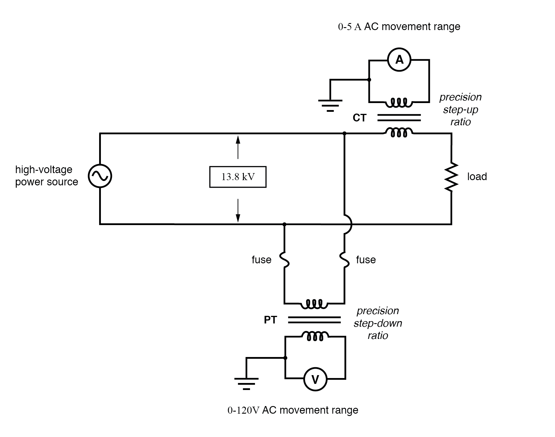
(CT) Current transformer scales current down. (PT) Potential transformer scales voltage down.
Shown here is a voltage and current meter panel from a three-phase AC system. The three “donut” current transformers (CT’s) can be seen in the rear of the panel. Three AC ammeters (rated 5 amps full-scale deflection each) on the front of the panel indicate current through each conductor going through a CT.
As this panel has been removed from service, there are no current-carrying conductors threaded through the center of the CT “donuts” anymore:
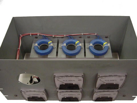
Toroidal current transformers scale high current levels down for application to 5 A full-scale AC ammeters.
Because of the expense (and often large size) of instrument transformers, they are not used to scale AC meters for any applications other than high voltage and high current. For scaling a milliamp or microamp movement to a range of 120 volts or 5 amps, normal precision resistors (multipliers and shunts) are used, just as with DC.
REVIEW:
- Polarized (DC) meter movements must use devices called diodes to be able to indicate AC quantities.
- Electromechanical meter movements, whether electromagnetic or electrostatic, naturally provide the average value of a measured AC quantity. These instruments may be ranged to indicate RMS value, but only if the shape of the AC waveform is precisely known beforehand!
- So-called true RMS meters use different technology to provide indications representing the actual RMS (rather than skewed average or peak) of an AC waveform.