Facebook
 Google
 GitHub
 Linkedin
AC Bridge Circuits
As we saw with DC measurement circuits, the circuit configuration known as a bridge can be a very useful way to measure unknown values of resistance.
This is true with AC as well, and we can apply the very same principle to the accurate measurement of unknown impedances.
How Does a Bridge Circuit Work?
To review, the bridge circuit works as a pair of two-component voltage dividers connected across the same source voltage, with a null-detector meter movement connected between them to indicate a condition of “balance” at zero volts:
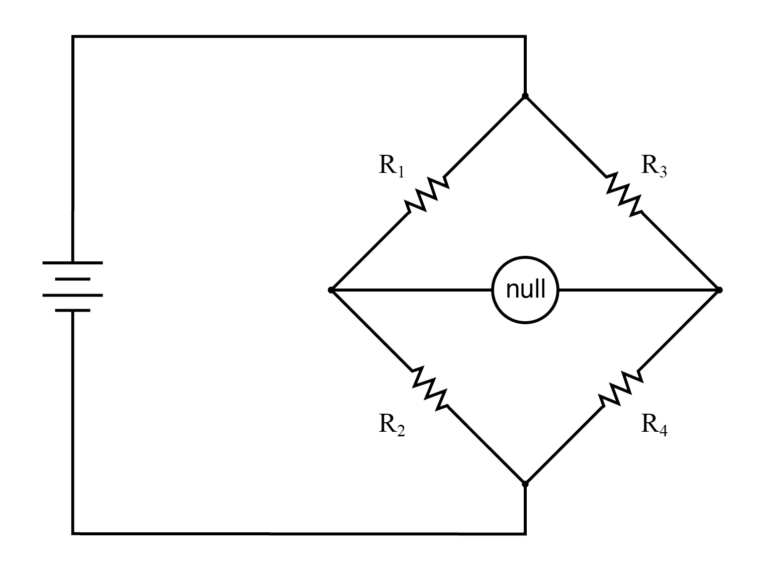
A balanced bridge shows a “null”, or minimum reading, on the indicator.
Anyone of the four resistors in the above bridge can be the resistor of unknown value, and its value can be determined by a ratio of the other three, which are “calibrated,” or whose resistances are known to a precise degree.
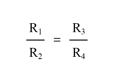
When the bridge is in a balanced condition (zero voltage as indicated by the null detector), the ratio works out to be this:
In a condition of balance:
One of the advantages of using a bridge circuit to measure resistance is that the voltage of the power source is irrelevant.
Practically speaking, the higher the supply voltage, the easier it is to detect a condition of imbalance between the four resistors with the null detector, and thus the more sensitive it will be.
A greater supply voltage leads to the possibility of increased measurement precision. However, there will be no fundamental error introduced as a result of a lesser or greater power supply voltage unlike other types of resistance measurement schemes.
Impedance Bridge
Impedance bridges work the same, only the balance equation is with complex quantities, as both magnitude and phase across the components of the two dividers must be equal in order for the null detector to indicate “zero.”
The null detector, of course, must be a device capable of detecting very small AC voltages. An oscilloscope is often used for this, although very sensitive electromechanical meter movements and even headphones (small speakers) may be used if the source frequency is within audio range.
Null Detector for AC
One way to maximize the effectiveness of audio headphones as a null detector is to connect them to the signal source through an impedance-matching transformer.
Headphone speakers are typically low-impedance units (8 Ω), requiring substantial current to drive, and so a step-down transformer helps “match” low-current signals to the impedance of the headphone speakers.
An audio output transformer works well for this purpose: (Figure below)
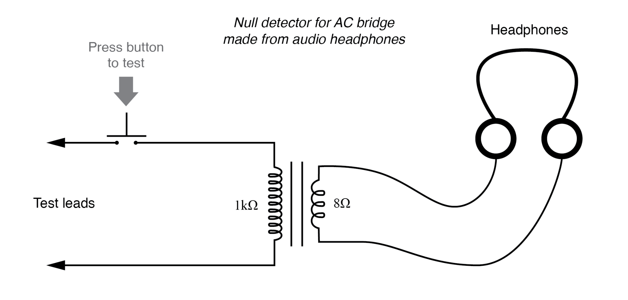
“Modern” low-Ohm headphones require an impedance matching transformer for use as a sensitive null detector.
Using a pair of headphones that completely surround the ears (the “closed-cup” type), I’ve been able to detect currents of less than 0.1 µA with this simple detector circuit.
The roughly equal performance was obtained using two different step-down transformers: a small power transformer (120/6 volt ratio), and an audio output transformer (1000:8 ohm impedance ratio).
With the pushbutton switch in place to interrupt current, this circuit is used for detecting signals from DC to over 2 MHz: even if the frequency is far above or below the audio range, a “click” will be heard from the headphones each time the switch is pressed and released.
Connected to a resistive bridge, the whole circuit looks like the figure below.
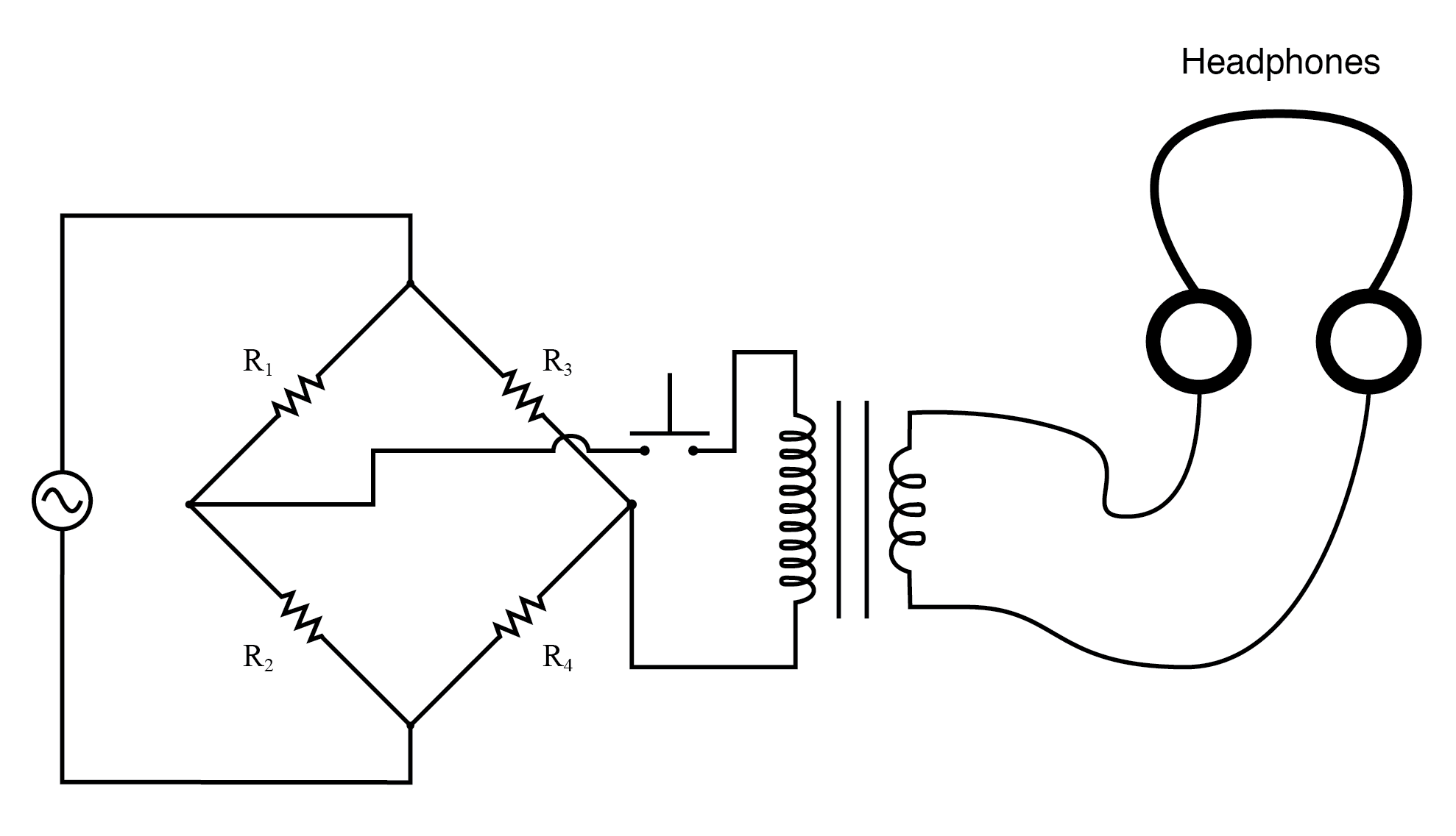
Bridge with sensitive AC null detector.
Listening to the headphones as one or more of the resistor “arms” of the bridge is adjusted, a condition of balance will be realized when the headphones fail to produce “clicks” (or tones, if the bridge’s power source frequency is within audio range) as the switch is actuated.
When describing general AC bridges, where impedances and not just resistances must be in the proper ratio for balance, it is sometimes helpful to draw the respective bridge legs in the form of box-shaped components, each one with a certain impedance: (Figure below)
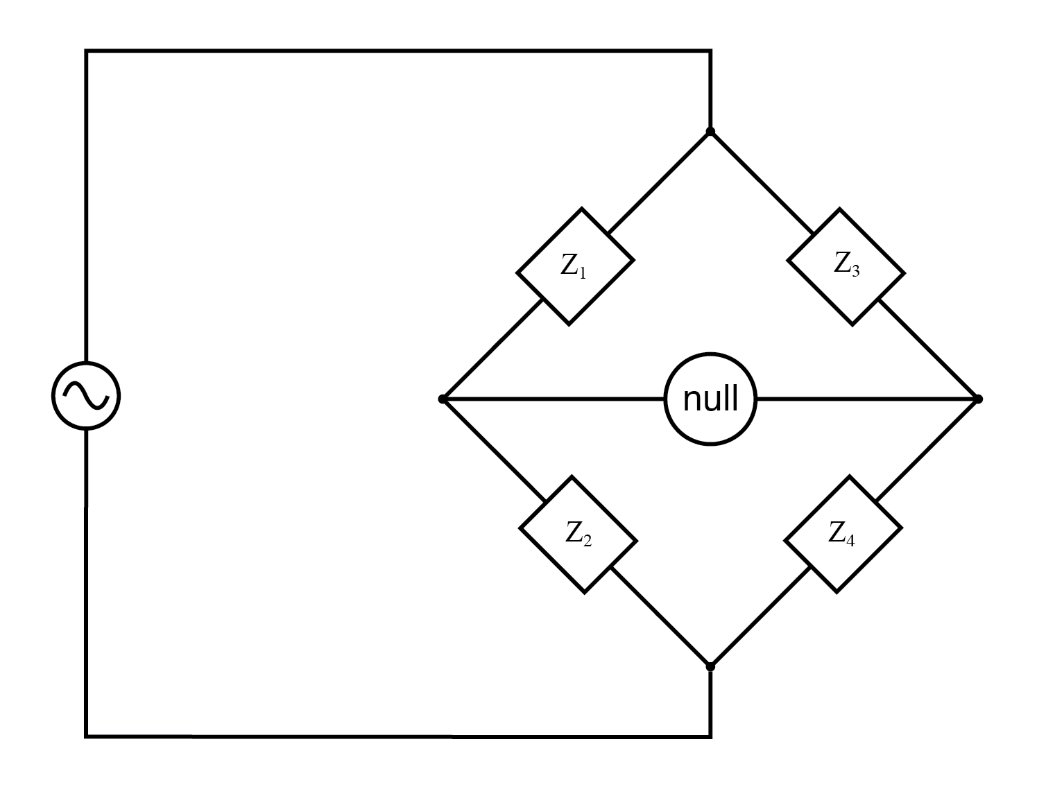
Generalized AC impedance bridge: Z = nonspecific complex impedance.
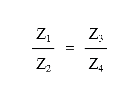
For this general form of the AC bridge to balance, the impedance ratios of each branch must be equal:
Again, it must be stressed that the impedance quantities in the above equation must be complex, accounting for both magnitude and phase angle.
It is insufficient that the impedance magnitudes alone be balanced; without phase angles in the balance as well, there will still be the voltage across the terminals of the null detector and the bridge will not be balanced.
Bridge circuits can be constructed to measure just about any device value desired, be it capacitance, inductance, resistance, or even “Q.”
As always in bridge measurement circuits, the unknown quantity is always “balanced” against a known standard, obtained from a high-quality, calibrated component that can be adjusted in value until the null detector device indicates a condition of balance.
Depending on how the bridge is set up, the unknown component’s value may be determined directly from the setting of the calibrated standard or derived from that standard through a mathematical formula.
Example of Bridge Circuits
A couple of simple bridge circuits are shown below, one for inductance (Figure below) and one for capacitance:
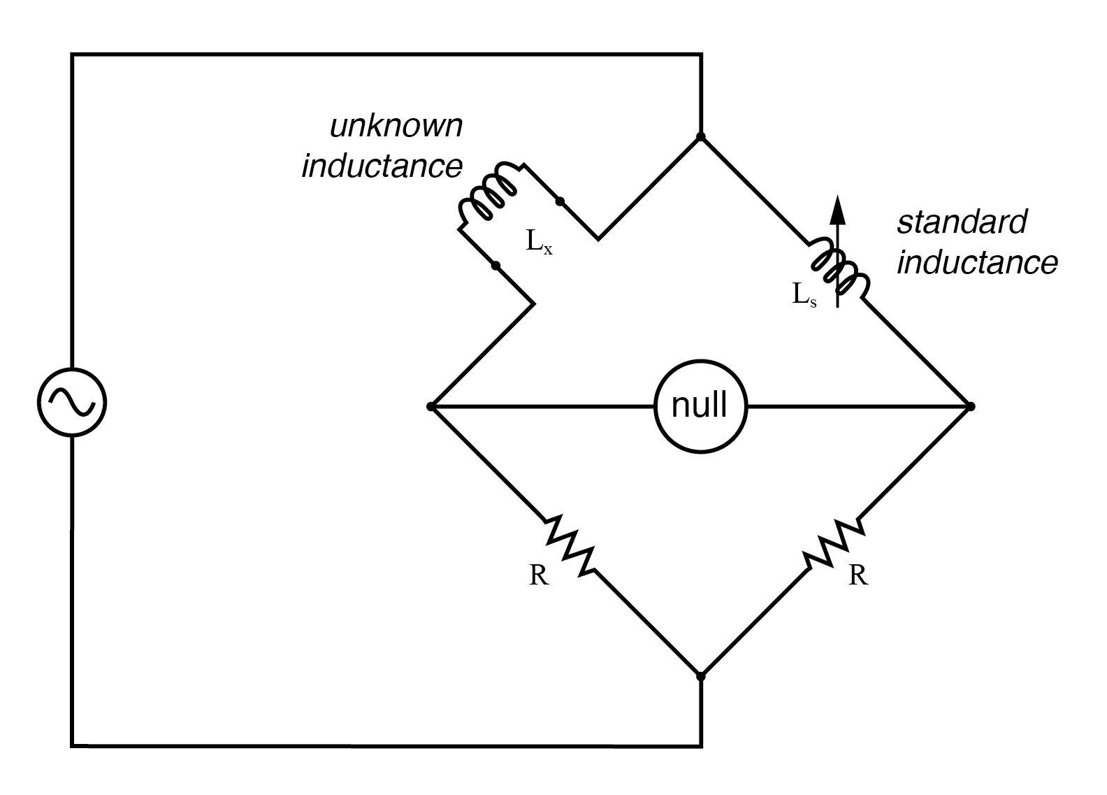
Symmetrical bridge measures unknown inductor by comparison to a standard inductor.
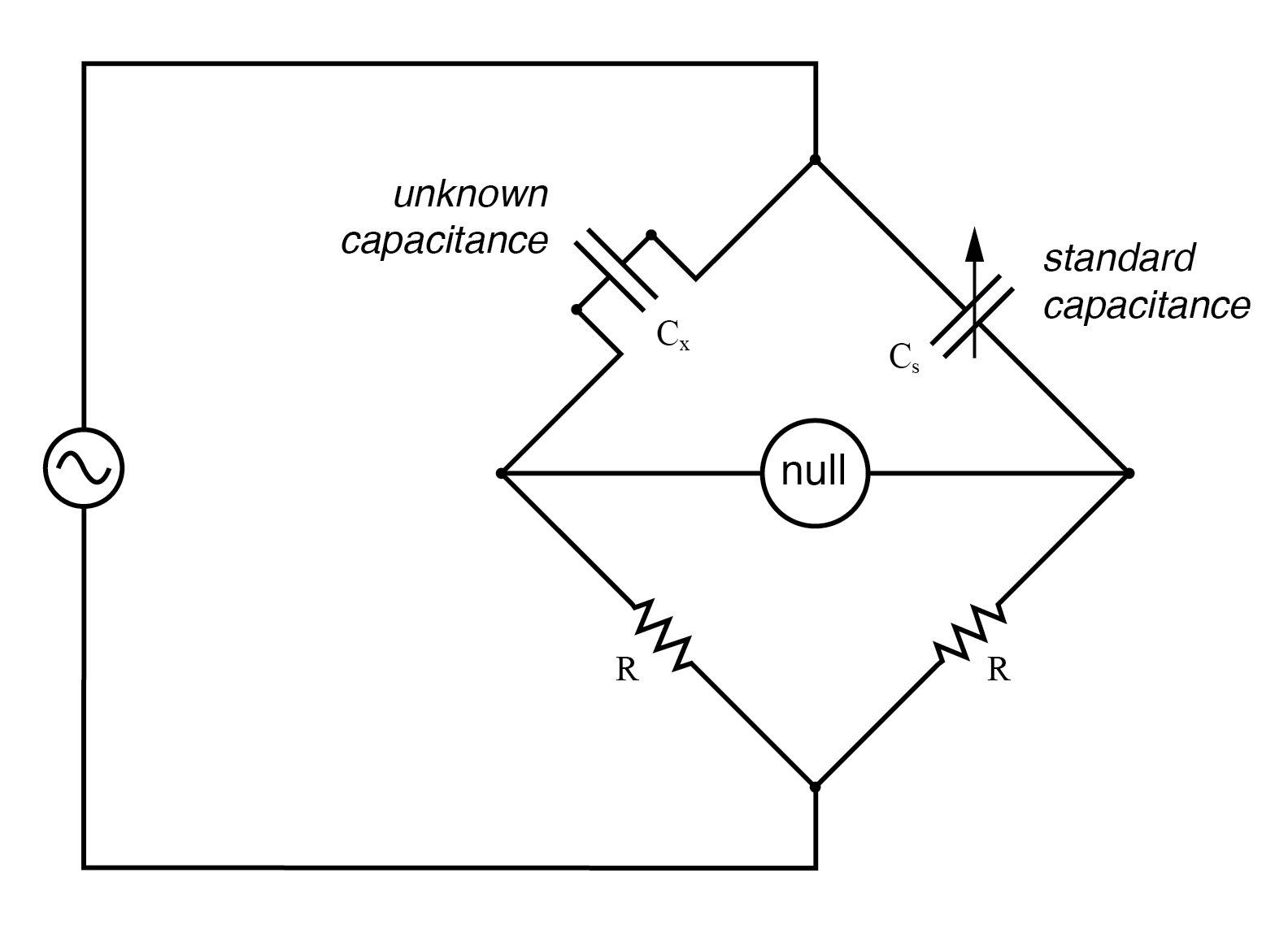
Symmetrical bridge measures unknown capacitor by comparison to a standard capacitor.
Simple “symmetrical” bridges such as these are so named because they exhibit symmetry (mirror-image similarity) from left to right.
The two bridge circuits shown above are balanced by adjusting the calibrated reactive component (Ls or Cs).
They are a bit simplified from their real-life counterparts, as practical symmetrical bridge circuits often have a calibrated, variable resistor in series or parallel with the reactive component to balance out stray resistance in the unknown component.
But, in the hypothetical world of perfect components, these simple bridge circuits do just fine to illustrate the basic concept.
Wien Bridge
An example of a little extra complexity added to compensate for real-world effects can be found in the so-called Wien bridge, which uses a parallel capacitor-resistor standard impedance to balance out an unknown series capacitor-resistor combination. (Figure below)
All capacitors have some amount of internal resistance, be it literal or equivalent (in the form of dielectric heating losses) which tend to spoil their otherwise perfectly reactive natures.
This internal resistance may be of interest to measure, and so the Wien bridge attempts to do so by providing a balancing impedance that isn’t “pure” either:
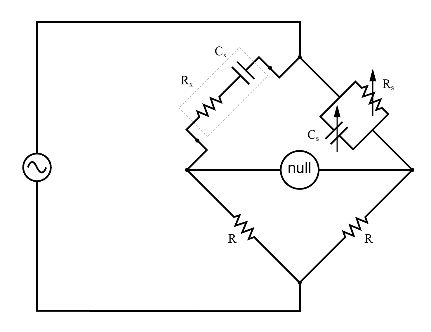
Wein Bridge measures both capacitive Cx and resistive Rx components of “real” capacitor.
Being that there are two standard components to be adjusted (a resistor and a capacitor) this bridge will take a little more time to balance than the others we’ve seen so far.
The combined effect of Rs and Cs is to alter the magnitude and phase angle until the bridge achieves a condition of balance.
Once that balance is achieved, the settings of Rs and Cs can be read from their calibrated knobs, the parallel impedance of the two determined mathematically, and the unknown capacitance and resistance determined mathematically from the balance equation (Z1/Z2 = Z3/Z4).
It is assumed in the operation of the Wien bridge that the standard capacitor has negligible internal resistance, or at least that resistance is already known so that it can be factored into the balance equation.
Wien bridges are useful for determining the values of “lossy” capacitor designs like electrolytics, where the internal resistance is relatively high.
They are also used as frequency meters because the balance of the bridge is frequency-dependent.
When used in this fashion, the capacitors are made fixed (and usually of equal value) and the top two resistors are made variable and are adjusted by means of the same knob.
An interesting variation on this theme is found in the next bridge circuit, used to precisely measure inductances.
Maxwell-Wein Bridge
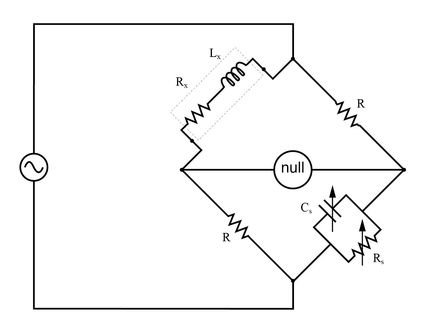
Maxwell-Wein bridge measures an inductor in terms of a capacitor standard.
This ingenious bridge circuit is known as the Maxwell-Wien bridge (sometimes known plainly as the Maxwell bridge) and is used to measure unknown inductances in terms of calibrated resistance and capacitance. (Figure above)
Calibration-grade inductors are more difficult to manufacture than capacitors of similar precision, and so the use of a simple “symmetrical” inductance bridge is not always practical.
Because the phase shifts of inductors and capacitors are exactly opposite each other, a capacitive impedance can balance out an inductive impedance if they are located in opposite legs of a bridge, as they are here.
Another advantage of using a Maxwell bridge to measure inductance rather than a symmetrical inductance bridge is the elimination of measurement error due to mutual inductance between two inductors.
Magnetic fields can be difficult to shield, and even a small amount of coupling between coils in a bridge can introduce substantial errors in certain conditions. With no second inductor to react within the Maxwell bridge, this problem is eliminated.
For the easiest operation, the standard capacitor (Cs) and the resistor in parallel with it (Rs) are made variable, and both must be adjusted to achieve balance.
However, the bridge can be made to work if the capacitor is fixed (non-variable) and more than one resistor made variable (at least the resistor in parallel with the capacitor, and one of the other two).
However, in the latter configuration, it takes more trial-and-error adjustment to achieve balance, as the different variable resistors interact in balancing magnitude and phase.
Unlike the plain Wien bridge, the balance of the Maxwell-Wien bridge is independent of source frequency, and in some cases, this bridge can be made to balance in the presence of mixed frequencies from the AC voltage source, the limiting factor being the inductor’s stability over a wide frequency range.
There are more variations beyond these designs, but a full discussion is not warranted here. General-purpose impedance bridge circuits are manufactured which can be switched into more than one configuration for maximum flexibility of use.
A potential problem in sensitive AC bridge circuits is that of stray capacitance between either end of the null detector unit and ground (earth) potential.
Because capacitances can “conduct” alternating current by charging and discharging, they form stray current paths to the AC voltage source which may affect bridge balance:
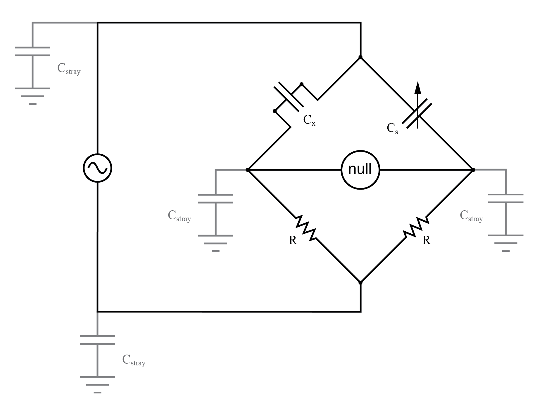
Stray capacitance to the ground may introduce errors into the bridge.
While reed-type meters are imprecise, their operational principle is not. In lieu of mechanical resonance, we may substitute electrical resonance and design a frequency meter using an inductor and capacitor in the form of a tank circuit (parallel inductor and capacitor).
One or both components are made adjustable, and a meter is placed in the circuit to indicate the maximum amplitude of the voltage across the two components.
The adjustment knob(s) are calibrated to show resonant frequency for any given setting, and the frequency is read from them after the device has been adjusted for the maximum indication on the meter.
Essentially, this is a tunable filter circuit which is adjusted and then read in a manner similar to a bridge circuit (which must be balanced for a “null” condition and then read).
The problem is worsened if the AC voltage source is firmly grounded at one end, the total stray impedance for leakage currents made far less and any leakage currents through these stray capacitances made greater as a result:
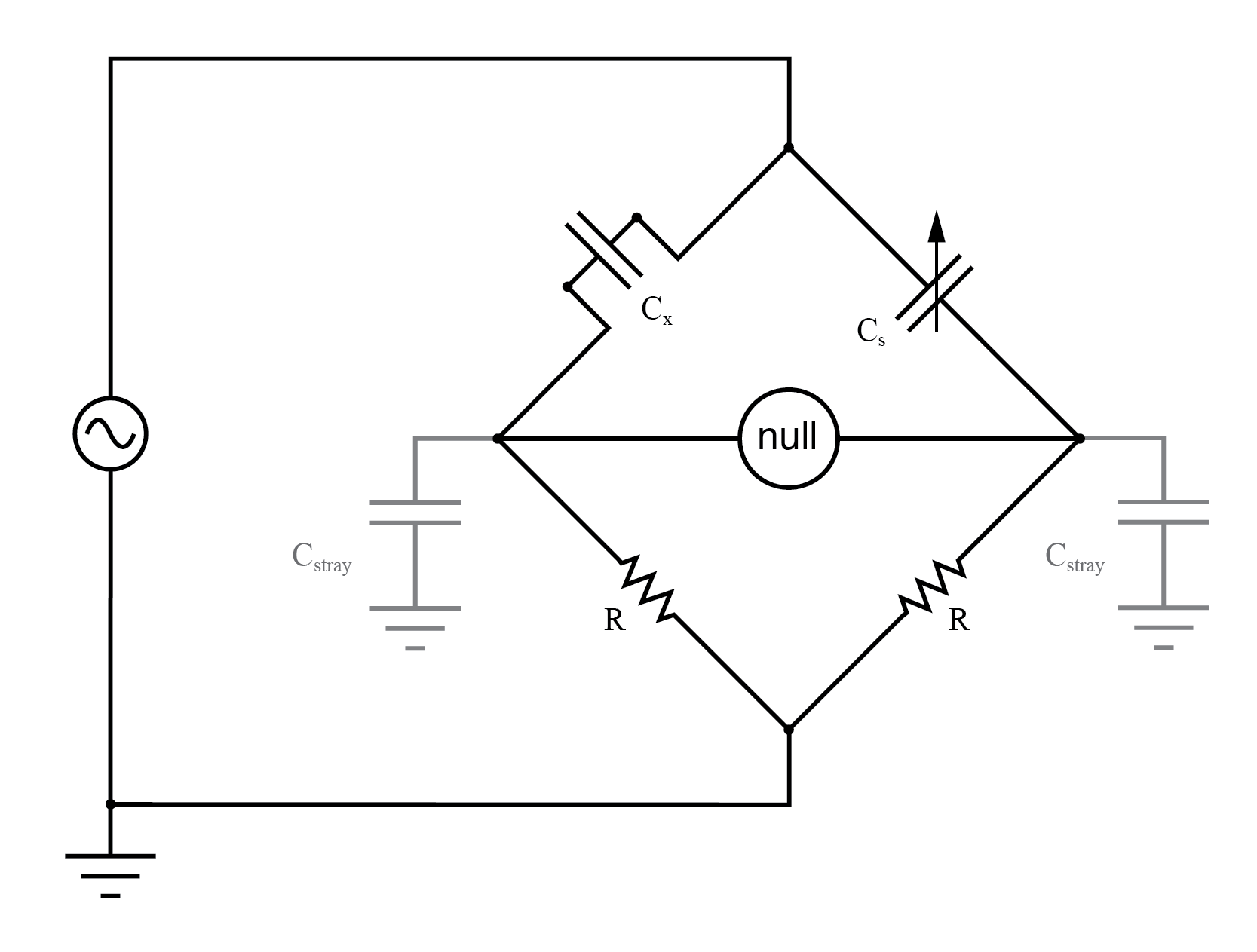
Stray capacitance errors are more severe if one side of the AC supply is grounded.
Wagner Ground
One way of greatly reducing this effect is to keep the null detector at ground potential, so there will be no AC voltage between it and the ground, and thus no current through stray capacitances.
However, directly connecting the null detector to the ground is not an option, as it would create a direct current path for stray currents, which would be worse than any capacitive path.
Instead, a special voltage divider circuit called a Wagner ground or Wagner earth may be used to maintain the null detector at ground potential without the need for a direct connection to the null detector. (Figure below)
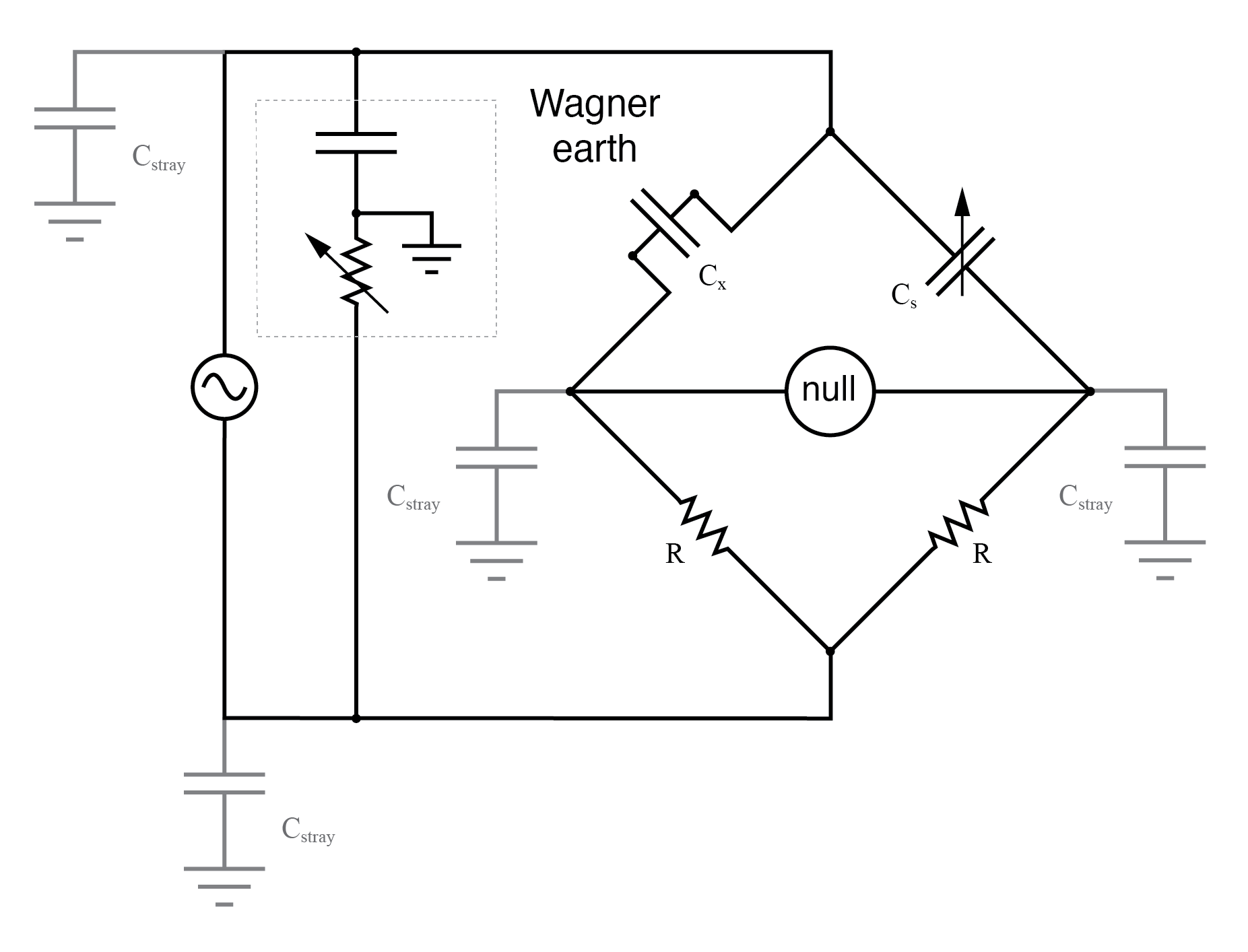
Wagner ground for AC supply minimizes the effects of stray capacitance to the ground on the bridge.
The Wagner earth circuit is nothing more than a voltage divider, designed to have the voltage ratio and phase shift as each side of the bridge.
Because the midpoint of the Wagner divider is directly grounded, any other divider circuit (including either side of the bridge) having the same voltage proportions and phases as the Wagner divider, and powered by the same AC voltage source, will be at ground potential as well.
Thus, the Wagner earth divider forces the null detector to be at ground potential, without a direct connection between the detector and ground.
There is often a provision made in the null detector connection to confirm the proper setting of the Wagner earth divider circuit: a two-position switch, (Figure below) so that one end of the null detector may be connected to either the bridge or the Wagner earth.
When the null detector registers zero signal in both switch positions, the bridge is not only guaranteed to be balanced, but the null detector is also guaranteed to be at zero potential with respect to ground, thus eliminating any errors due to leakage currents through stray detector-to-ground capacitances:
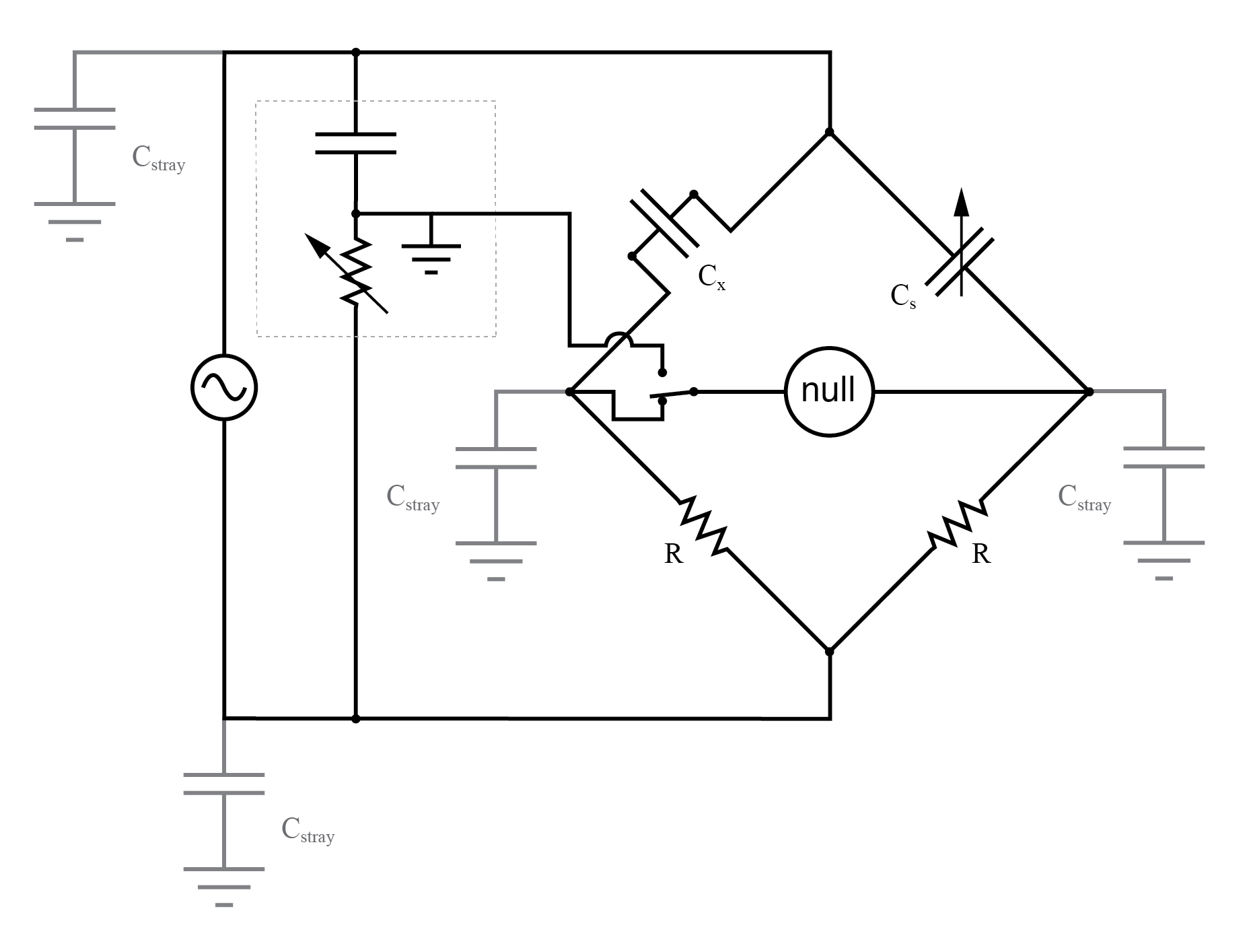
The switch-up position allows adjustment of the Wagner ground.
REVIEW:
- AC bridge circuits work on the same basic principle as DC bridge circuits: that a balanced ratio of impedances (rather than resistances) will result in a “balanced” condition as indicated by the null-detector device.
- Null detectors for AC bridges may be sensitive electromechanical meter movements, oscilloscopes (CRT’s), headphones (amplified or unamplified), or any other device capable of registering very small AC voltage levels. Like DC null detectors, its only required point of calibration accuracy is at zero.
- AC bridge circuits can be of the “symmetrical” type where an unknown impedance is balanced by a standard impedance of similar type on the same side (top or bottom) of the bridge. Or, they can be “nonsymmetrical,” using parallel impedances to balance series impedances, or even capacitances balancing out inductances.
- AC bridge circuits often have more than one adjustment, since both impedance magnitude and phase angle must be properly matched to balance.
- Some impedance bridge circuits are frequency-sensitive while others are not. The frequency-sensitive types may be used as frequency measurement devices if all component values are accurately known.
- A Wagner earth or Wagner ground is a voltage divider circuit added to AC bridges to help reduce errors due to stray capacitance coupling the null detector to ground.
RELATED WORKSHEETS: