Facebook
 Google
 GitHub
 Linkedin
AC Lab - Phase Shift in a Capacitive Circuit
Project Overview
Reactive components like inductors and capacitors create a frequency-dependent phase shift. The simple AC circuit illustrated in Figure 1 will be used to demonstrate the phase shift.
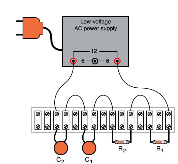
Figure 1. Implementation of the AC phase shift circuit using terminal strips.
Parts and Materials
- Low-voltage AC power supply
- Two capacitors, 0.1 µF each, non-polarized
- Two 27 kΩ resistors
I recommend ceramic disk capacitors because they are insensitive to polarity (non-polarized), inexpensive, and durable. Avoid capacitors with any kind of polarity marking, as these will be destroyed when powered by AC.
Learning Objectives
- How out-of-phase AC voltages do not add algebraically, but according to vector (phasor) arithmetic
Instructions
Step 1: Build the circuit illustrated in Figure 1 and represented by the schematic diagram in Figure 2.
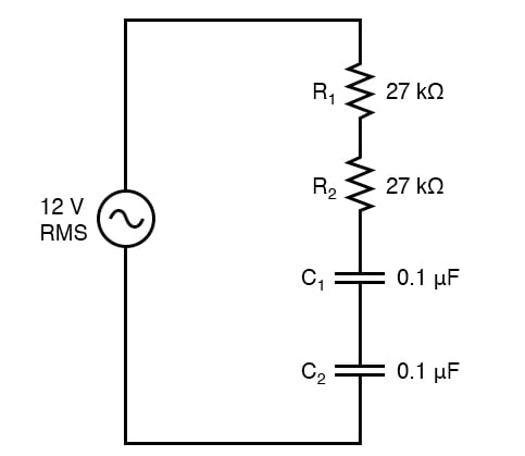
Figure 2. AC phase shift circuit schematic diagram.
Step 2: Measure the voltage drops across each component with an AC voltmeter. Add the measured AC voltages together.
Step 3: Measure the total (supply) voltage with the same voltmeter. You will discover that the sum of the voltage drops does not equal the supply voltage. This is due to phase shifts in the circuit: voltage dropped across the capacitors is out-of-phase with voltage dropped across the resistors, and thus the voltage drop figures do not add up as one might expect. Taking phase angle into consideration, they do add up to equal the total, but a voltmeter doesn’t provide phase angle measurements, only amplitude.
Step 4: Try measuring the voltage dropped across both resistors at once. This voltage drop will equal the sum of the voltage drops measured across each resistor separately. This tells you that both the resistors’ voltage drop waveforms are in-phase with each other since they add simply and directly.
Step 5: Measure the voltage dropped across both capacitors at once. This voltage drop, like the drop measured across the two resistors, will equal the sum of the voltage drops measured across each capacitor separately. Likewise, this tells you that both the capacitors’ voltage drop waveforms are in-phase with each other.
Step 6: Given that the power supply frequency is 60 Hz (assuming household power frequency in the United States), calculate impedances for all components and determine all voltage drops using Ohm’s Law and the impedance values for the capacitors:
$$Z_C = \frac{1}{2\pi fC} = \frac{1}{2 \pi \cdot 60 \cdot 0.1E-6} = 26.526 \text{ k}\Omega $$
$$Z_{total} = 27 + 27 + 26.526 + 26.526 = 107.052 \text{ k}\Omega $$
$$I = \frac{V}{Z_{total}} = \frac{12}{107052} = 112.1 \text{ } \mu \text{A}$$
$$V_C = I \cdot Z_C = (\text{112.1E-06})\cdot(26526) = 2.97 \text{ V}$$
$$V_R = I \cdot R = (\text{112.1E-06})\cdot(27000) = 3.03 \text{ V}$$
$$V_{total} = 2 \cdot (V_R + V_C) = 2 \cdot (3.03 + 2.97) = 12.0 \text{ V}$$
The polar magnitudes of these calculated results should closely agree with your voltmeter readings.
SPICE Simulation of the AC Phase Shift Circuit
We can simulate our simple phase shift circuit using the schematic diagram of Figure 3 with node numbers and the following netlist.
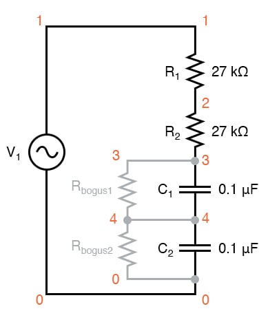
Figure 3. AC phase shift circuit schematic diagram for SPICE simulation.
The two large-value resistors Rbogus1 and Rbogus1 are connected across the capacitors to provide a DC path to the ground in order that SPICE will work. This is a workaround for one of SPICE’s quirks to avoid it from seeing the capacitors as open circuits in its analysis. These two resistors are entirely unnecessary in the real circuit.
Netlist (make a text file containing the following text, verbatim):
Phase shift circuit
v1 1 0 ac 12 sin
r1 1 2 27k
r2 2 3 27k
c1 3 4 0.1u
c2 4 0 0.1u
rbogus1 3 4 1e9
rbogus2 4 0 1e9
.ac lin 1 60 60
* Voltage across each component:
.print ac v(1,2) v(2,3) v(3,4) v(4,0)
* Voltage across pairs of similar components
.print ac v(1,3) v(3,0)
.end
Related Content
Learn more about the fundamentals behind this project in the resources below.
Technical Articles:
Textbook:
Worksheets: