Facebook
 Google
 GitHub
 Linkedin
AC Lab - Automotive Alternator as AC Generator
Project Overview
With a little wiring, automotive alternators can be converted to three-phase AC generators, as illustrated in Figure 1.
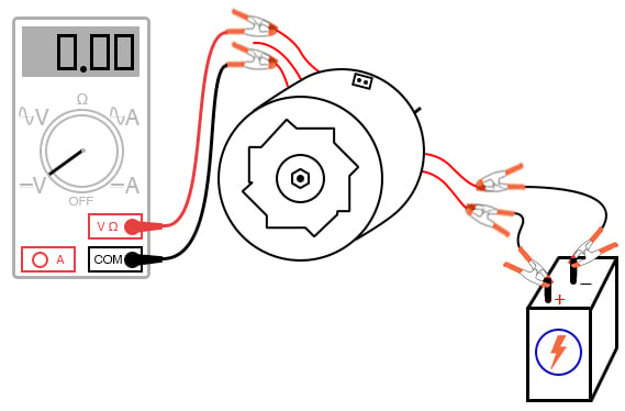
Figure 1. Using an automotive alternator as a generator.
If you obtain two alternators, you may use one as a generator and the other as a motor, as described in an optional portion of this project. The steps needed to prepare an alternator as a three-phase generator and as a three-phase motor are the same, making the process easy to replicate.
Parts and Materials
- Automotive alternator (one required, but two recommended)
- Heavy gauge wire (at least 20 gauge)
Old alternators may be obtained for low prices at automobile wrecking yards. Many yards have alternators already removed from the automobile for your convenience. I do not recommend paying full price for a new alternator, as used units cost far less money and function just as well for the purposes of this experiment.
Additionally, I highly recommend using a Delco-Remy brand of alternator. This is the type used on General Motors (GMC, Chevrolet, Cadillac, Buick, Oldsmobile) vehicles. One particular model has been produced by Delco-Remy since the early 1960s with few design changes. It is also a fairly common unit to locate in a wrecking yard and easy to work with.
Learning Objectives
- To determine the effects of electromagnetism
- To determine the effects of electromagnetic induction
- To illustrate the construction of real electromagnetic machines
- To illustrate the construction and application of three-phase windings
Alternator Theory of Operation
An automotive alternator is a three-phase generator with a built-in rectifier circuit consisting of six diodes, as shown in Figure 2.

Figure 2. Automotive alternator schematic diagram
As the sheave (most people call it a pulley) is rotated by a belt connected to the automobile engine’s crankshaft, a magnet is spun past a stationary set of three-phase windings (called the stator), usually connected in a Y configuration.
The spinning magnet is actually an electromagnet, not a permanent magnet. Alternators are designed this way so that the magnetic field strength can be controlled so that output voltage may be controlled independently of rotor speed.
This rotor magnet coil (called the field coil, or simply field) is energized by battery power so that it takes a small amount of electrical power input to the alternator to get it to generate a lot of output power. Electrical power is conducted to the rotating field coil through a pair of copper slip rings mounted concentrically on the shaft, contacted by stationary carbon brushes. The brushes are held in firm contact with the slip rings by spring pressure.
Many modern alternators are equipped with built-in regulator circuits that automatically switch battery power on and off to the rotor coil to regulate the output voltage. This circuit, if present in the alternator you choose for the experiment, is unnecessary and will only impede your study if left in place. Feel free to remove it, just make sure you leave access to the brush terminals so that you can power the field coil with the alternator fully assembled.
Instructions
Step 1: First, consult an automotive repair manual on the specific details of your alternator. The documentation provided in the book you’re reading now is as general as possible to accommodate different brands of alternators. You may need more specific information, and a service manual is the best place to obtain it.
Step 2: For this experiment, you’ll be connecting wires to the coils inside the alternator and extending them outside the alternator case for easy connection to test equipment and circuits. Unfortunately, the connection terminals provided by the manufacturer won’t suit our needs here, so you need to make your own connections.
Disassemble the unit and locate terminals for connecting to the two carbon brushes (Figure 3).

Figure 3. Connecting wires to the brushes and stator windings
Solder a pair of wires to these terminals (at least 20 gauge in size) and extend these wires through vent holes in the alternator case, making sure they won’t get snagged on the spinning rotor when the alternator is re-assembled and used.
Step 3: Locate the three-phase line connections coming from the stator windings and connect wires to them as well, extending these wires outside the alternator case through some vent holes (Figure 3). Use the largest gauge wire that is convenient to work with for these wires, as they may be carrying substantial current.
As with the field wires, route them in such a way that the rotor will turn freely with the alternator reassembled. The stator winding line terminals are easy to locate. All three of them connect to three terminals on the diode assembly, usually with ring-lug terminals soldered to the ends of the wires.
Step 4: I recommend that you solder ring-lug terminals to your wires and attach them underneath the terminal nuts along with the stator wire ends so that each diode block terminal is securing two ring lugs.
Step 5: Re-assemble the alternator, taking care to secure the carbon brushes in a retracted position so that the rotor doesn’t damage them upon re-insertion. On Delco-Remy alternators, a small hole is provided on the back case half and also at the front of the brush holder assembly, through which a paper clip or thin-gauge wire may be inserted to hold the brushes back against their spring pressure. Consult the service manual for more details on alternator assembly.
Step 6: When the alternator has been assembled, try spinning the shaft and listening for any sounds indicative of colliding parts or snagged wires. If there is any such trouble, take it apart again and correct whatever is wrong.
Step 7: If and when it spins freely as it should, connect the two field wires to a 6 V battery, as shown in Figure 4.
Figure 4. Connecting a battery and voltmeter to the alternator.
Step 8: Connect a voltmeter to any two of the three-phase line connections (Figure 4). With the multimeter set to the DC volts function, slowly rotate the alternator shaft. The voltmeter reading should alternate between positive and negative as the shaft is turned: a demonstration of very slow alternating voltage (AC voltage) being generated.
Step 9: If step 8 is successful, switch the multimeter to the AC volts setting and try again. Try spinning the shaft slowly and then faster, comparing voltmeter readings between the two conditions.
Step 10: Short-circuit any two of the three-phase line wires and try spinning the alternator. What you should notice is that the alternator shaft becomes more difficult to spin. The heavy electrical load you’ve created via the short circuit causes a heavy mechanical load on the alternator, as mechanical energy is converted into electrical energy.
Step 11: Now, try connecting 12 V DC to the field wires. Repeat the DC voltmeter, AC voltmeter, and short-circuit tests described above. What difference(s) do you notice?
Step 12: Find some sort of polarity-insensitive 6 or 12 V loads, such as small incandescent lamps, and connect them to the three-phase line wires. Wrap a thin rope or heavy string around the groove of the sheave (pulley) and spin the alternator rapidly, and the loads should function.
Connecting a Second Alternator as a Motor (Optional)
Step 13: If you have a second alternator, modify it as you modified the first one, connecting five of your own wires to the field brushes and stator line terminals, respectively. You can then use it as a three-phase motor powered by the first alternator, as shown in Figure 5.

Figure 5. Driving a motor (made from an alternator) with a generator (made from an alternator).
Connect each of the three-phase line wires of the first alternator to the respective wires of the second alternator.
Step 14: Connect the field wires of one alternator to a 6 V battery (Figure 5). This alternator will be the generator.
Step 15: Wrap rope around the sheave in preparation to spin it. Take the two field wires of the second alternator and short them together (Figure 5). This alternator will be the motor.
Step 16: Spin the generator shaft while watching the motor shaft’s rotation.
Step 17: Try reversing any two of the three-phase line connections between the two units and spin the generator again. What is different this time?
Step 18: Connect the field wires of the motor unit to the 6 V battery. You may parallel-connect this field with the field of the generator unit across the same battery terminals, if the battery is strong enough to deliver several amps of current, both coils will draw together. This will magnetize the rotor of the motor. Try spinning the generator again and note any differences in operation.
In the first motor setup, where the field wires were simply shorted together, the motor was functioning as an induction motor. In the second setup, where the motor’s rotor was magnetized, it functioned as a synchronous motor.
Take Your Modified Alternator to the Next Level
If you are feeling particularly ambitious and are skilled in metal fabrication techniques, you may make your own high-power generator platform by connecting the modified alternator to a bicycle, as illustrated in Figure 6.

Figure 6. Design of a high-power generator using a modified bicycle.
I’ve built an arrangement like this, as shown in Figure 7.

Figure 7. Example of a high-power generator using a modified bicycle.
The rear wheel drives the generator sheave with a long v-belt. This belt also supports the rear of the bicycle, maintaining constant tension when a rider is pedaling the bicycle.
The generator hangs from a steel support structure (I used welded 2-inch square tubing, but a frame could be made out of lumber). Not only is this machine practical, but it is reliable enough to be used as an exercise machine, and it is inexpensive to make.
In Figure 7, you can see a bank of three 12 V RV light bulbs on the floor behind the bicycle unit (in the lower-left corner of the photograph). These bulbs function as a load when riding the bicycle as an exercise machine. A set of three switches is mounted at the front of the bicycle, where I can turn loads on and off while riding.
By rectifying the three-phase AC power produced, it is possible to have the alternator power its own field coil with DC voltage, eliminating the need for a battery. However, some independent source of DC voltage will still be necessary for start-up, as the field coil must be energized before any AC power can be produced.
Related Content
Learn more about the fundamentals behind this project in the resources below.
Textbook
Worksheets: