 Facebook
 Google
 GitHub
 Linkedin
Understanding Phase Shift in Analog Circuits
Learn about phase shift and how this fundamental electrical phenomenon is related to different circuit configurations.
Learn about phase shift and how this fundamental electrical phenomenon is related to different circuit configurations.
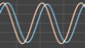
This article talks about phase shift, the effect of a circuit to cause a lead or lag of voltage or current from its input to its output. In particular, we’re going to concern ourselves with how reactive loads and networks will affect the phase shift of a circuit. Phase shift can have all sorts of consequences, whether you're working with oscillators, amplifiers, feedback loops, filters, or the like. You expect your inverting op-amp circuit to have 180° phase shift, and instead it returns an in-phase signal and causes frustrating oscillation problems. Probing the circuit might change the effect further. Maybe you have a resonant tank that is used in a feedback loop for an oscillator, but the tank provides only 90° of phase shift, whereas you need 180°. You have to change the tank, but how?
Phase Shift for Reactive Loads
Frequency-dependent phase shift originates with reactive components: capacitors and inductors. It is a relative quantity, and thus it must be given as a difference in phase between two points. In this article, "phase shift" will refer to the difference in phase between the output and the input. It's said that a capacitor causes a 90° lag of voltage behind current, while an inductor causes a 90° lag of current behind voltage. In phasor form, this is represented by the +j or -j in the inductive and capacitive reactance, respectively. But capacitance and inductance exist in all conductors to some extent. So why don't they all cause 90° phase shifts?
All of our phase shift effects are going to be modeled by RC and RL circuits. All circuits can be modeled as a source, with some source impedance, feeding the circuit, and a load following the circuit. The source impedance of the source is also called its output impedance. I find it easiest to talk about input and output impedance, and to talk about stages, so let me rephrase: All circuits can be modeled as an output of one stage with some output impedance, feeding the present stage, being loaded by the input impedance of the following stage. This is significant, because it reduces complex networks to much simpler RLC circuits, filters, and voltage dividers.
Take a look at the following circuit.
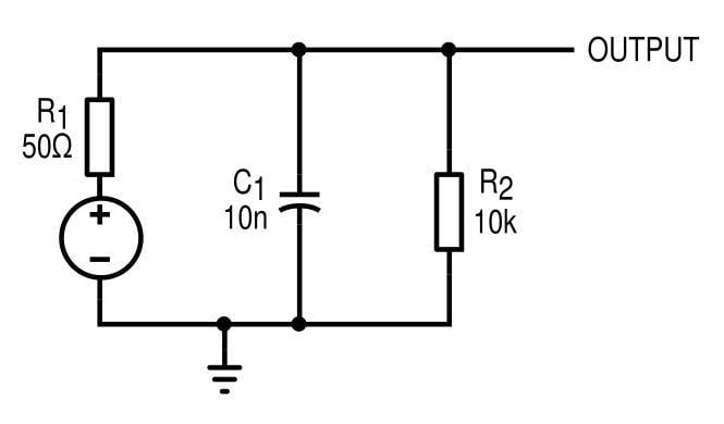
Figure 1. A capacitor shunting the previous stage, and a 10 kΩ load.
This is going to model some source circuit (like an amplifier) with an output impedance of 50 Ω, which has a 10 kΩ load and is shunted by a 10 nF capacitor. What should be clear here is that the circuit, essentially, is an RC low-pass filter made of R1 and C1. We know from basic circuit analysis that the voltage phase shift in an RC circuit will vary from 0° to -90°, and simulation confirms this.
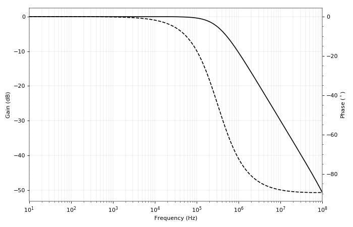
Figure 2. Bode plot of the output of our shunt capacitor circuit.
For low frequencies, the output phase is unaffected by the capacitor. As we get to the cutoff frequency (fc) of the RC filter, the phase drops through -45°. For frequencies beyond the cutoff frequency, the phase approaches its asymptotic value of -90°.
This response models the phase shift caused by every shunt capacitor. A shunt capacitor will cause between 0° and -90° phase shift on a resistive load. It’s important to be aware of the attenuation too, of course.
A similar look at a series capacitor (for example, an AC-coupling cap) shows the typical effect for that configuration.
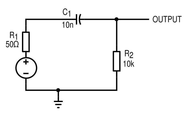
Figure 3. Series capacitor circuit...
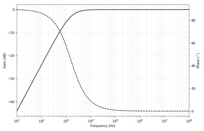
Figure 4. ... And its bode plot
In this case, the phase shift starts at +90°, and the filter is a high-pass. Beyond the cutoff frequency, we eventually settle to 0°. So we see a series capacitor will always contribute between +90° and 0° phase shift.
A Common-Emitter Amplifier
With this information at our disposal, we can apply an RC model to any circuit we wish. For example, this common-emitter amplifier.
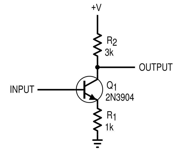
Figure 5. Common-emitter amplifier with emitter degeneration resistance (bias not shown)
The response of this amplifier is flat up to around 10 MHz.
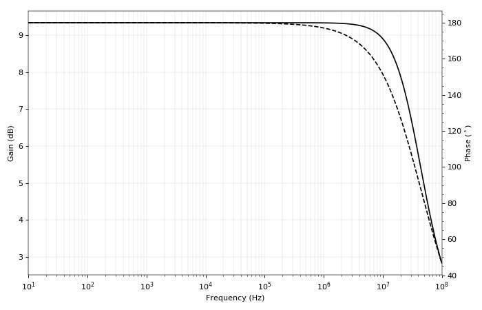
Figure 6. Bode plot for the common-emitter amplifier
Only after 10 MHz or so do we see changes in phase shift—below that it’s 180°, which is what we expect since the common-emitter configuration is an inverting amplifier. The output impedance of the amplifier, neglecting the Early effect, is R2 = 3 kΩ, which is pretty high. Now we put a shunt capacitor on the output. What can we expect to happen to the phase?
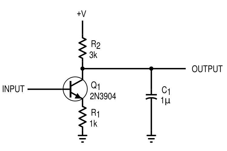
Figure 7. Common-emitter amplifier with a shunt capacitor
From our experience, we would expect there to be a cutoff frequency of 53 Hz, below which there should be a 180° phase shift (no effect from capacitor) and above which there would be 180° - 90° = 90° phase shift (as well as a lot of loss). Simulation confirms our suspicions:
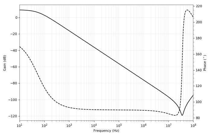
Figure 8. Bode plot for the output of the capacitively loaded common-emitter amplifier
Note that this is equivalent to if the phase were -180° going to -270°. Now we’re starting to see that driving a capacitive load can cause unexpected phase changes, which might wreak havoc on an unexpecting feedback amplifier.
A more common scenario finds a series coupling capacitor on the output, as shown in the next schematic.
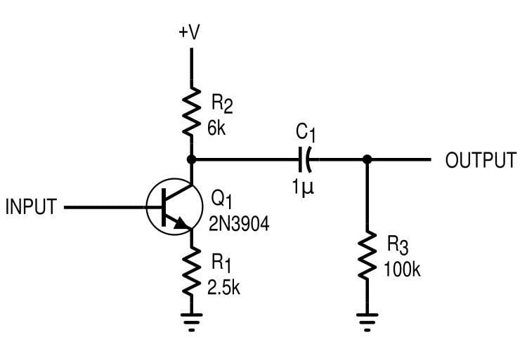
Figure 9. Common-emitter amplifier with a series AC-coupling capacitor
I've changed the circuit values and added a resistive load of 100 kΩ. Now we have a high-pass filter composed of C1 and R3, with a cutoff frequency of only 1.6 Hz. We expect that the phase shift will be -90° below 1.6 Hz, and -180° well above it, and this is confirmed with simulation.
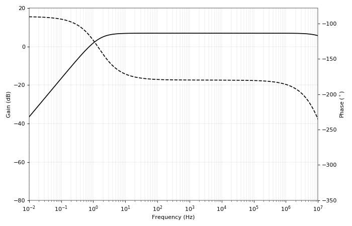
Figure 10. Bode plot for the CE amplifier with an AC-coupling capacitor
This would be a good choice of coupling capacitor for audio-frequency signals, because the -90° phase shift region (and hence the attenuation) is well below 10 Hz.
These sorts of effects aren’t limited to capacitors, of course. Inductors will have an opposite reaction: shunt inductors cause between 0° (below fc) and +90° (well above fc) phase shift, while series inductors cause between 0° (above fc) and -90° (below fc) phase shift. We must be careful, however, not to create any problematic ground connections, because inductors are going to be shorts at DC.
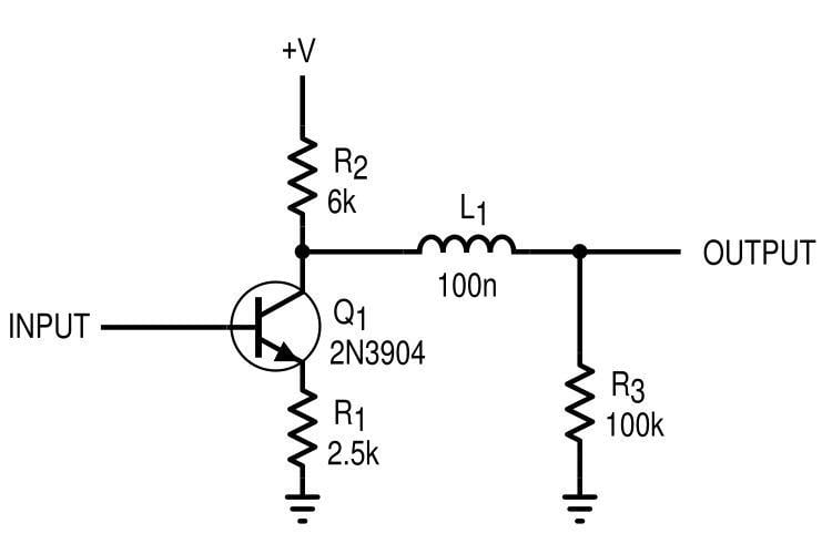
Figure 11. Output inductor in the common-emitter amplifier. This series inductor will have very little effect on the circuit at low frequencies. High frequencies might not be so lucky.
Conclusion
We've laid the groundwork for understanding phase shift in analog circuits. By looking at the output of a circuit as a source with output impedance, we can effectively model the effects of reactive loads on circuit phase. Both passive and active circuits can be modeled in this way, giving us useful tools for simple analysis and design. In the next article, we'll test these concepts further by applying them to op-amp circuits and resonant networks.
Related Content


A Good post to understand phase shifts and also to brush up amplifier frequency responses.
Thank you very Sam. I’ve never had so clear. Excellent tutorial.