Facebook
 Google
 GitHub
 Linkedin
How Reactive Loads and Networks Affect Phase Shift in Analog Circuits
How can reactive elements affect phase shift in an LC circuit? Learn more about phase shift in analog design.
How can reactive elements affect phase shift in an LC circuit? Learn more about phase shift in analog design.
This article is going to talk about phase shift, the effect of a circuit to cause a lead or lag of voltage or current from its input to its output. In particular, we’re going to concern ourselves with how reactive loads and networks will affect the phase shift of a circuit.
We'll specifically take a look at how phase shift can affect otherwise perfectly reliable op-amps and how to use reactive elements to our advantage in some resonant network topologies.
This is a continuation of an article on phase shift in analog circuits, so please consider reviewing it before reading on.
A Capacitive Load on a Buffer
In the last article, we saw how to model phase-shift caused by reactive elements in a circuit. Now, let's apply what we've learned so far to an op-amp circuit.
Below is an op-amp acting as a simple buffer.
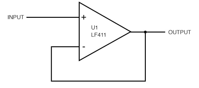
Figure 1. A basic buffer, or “voltage follower,” that uses the LF411 op-amp.
The response is even and flat up to 1 MHz before the phase starts to fall off.
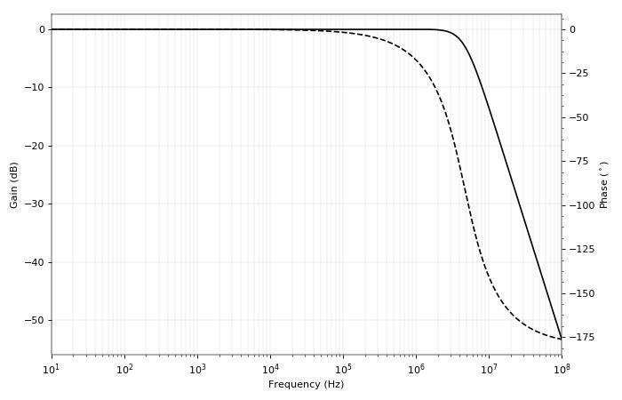
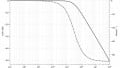
Figure 2. Output response of the LF411 voltage follower. It starts to attenuate the signal at about 4 MHz.
This circuit is relying on negative feedback (in-phase output to inverting input), and that -180° phase shift causes the negative feedback to turn into positive feedback (180° phase shifted output to inverting input).
Now let's try loading the circuit with a capacitor.
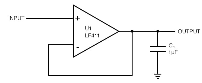
Figure 3. Using the buffer to drive a very large capacitive load. This is not a good idea!
If the op-amp has a resistive output impedance, which for this op-amp (the LF411) at unity gain is about 0.1 - 10 Ω, we expect that capacitor to cause -90° phase shift above the cutoff frequency. Let's see what happens.
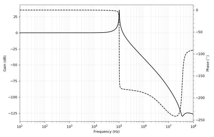
Figure 4. Evidence of capacitive evils: the amplifier is going oscillate!
That looks bad. The amplitude response has a resonant peak, and the phase snaps down to -180°, a perfect recipe for oscillation. There must be at least three capacitances (inductances are unlikely) causing these changes in response. With our suspect in hand, we can go through the circuit and track down what exactly is causing the problem.
Achieving Phase Shift with Reactive Networks
Phase shift becomes particularly important in circuits like feedback networks, resonant networks, and oscillators. We might desire to have a 90° phase shift in our circuit to intentionally steer the phase. Simple enough, we can add a capacitor (or for the adventurous, an inductor) shunting the output and see where that gets us.
In fact, we might not want only a 90° phase shift on our load. Maybe we want 180°.
Maybe we'll just throw a second capacitor in?

Figure 5. An innocent attempt at creating a 180° phase shift
That doesn't work—the two parallel capacitors just form an equivalent capacitor. They both share the same voltage, so they can't both contribute different amounts of lag. We'll need to be more creative.
One way to achieve such an effect is with several stages of RC filters. But the more desirable route may be to separate the capacitors with one or more reactive elements, as in the following circuit.
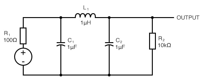
Figure 6. Remedying the problem, this circuit should have a 180° phase shift at resonance.
This circuit is a low-pass filter, which will resonate at the same frequency as a resonant network made up of a 1 µF capacitor and a 0.5 µH inductor (or a 0.5 µF capacitor with a 1 µH inductor).
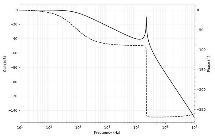
Figure 7. The Bode plot for the C-L-C network shows good resonance and rapid change in phase.
We see from the response and phase shift that the circuit behaves like an RC filter with the source resistor and both capacitors in parallel, reaching -90° shortly before the resonant peak. Then the resonant peak occurs, and the phase snaps down to -270° (maximum phase shift from three reactive elements). Exactly at resonance, the phase shift is the desired 180°.
This circuit is used as the resonant element in Colpitts oscillators, and the inductor-capacitor-inductor variant is used in Hartley oscillators. Often times, the circuit will be drawn as shown in Figure 8.
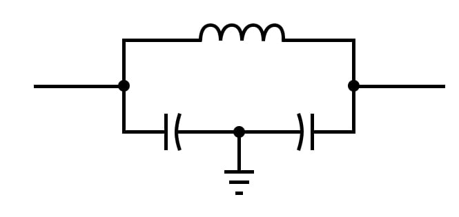
Figure 8. An alternate drawing of the C-L-C circuit, often seen in the Colpitts oscillator schematic diagram.
While it may slightly obfuscate the purpose of the elements, drawing the elements as in Figure 8 gives the appearance of a single resonating element. You can see an example of a Colpitts oscillator with the resonant network drawn in this manner in Figure 9.
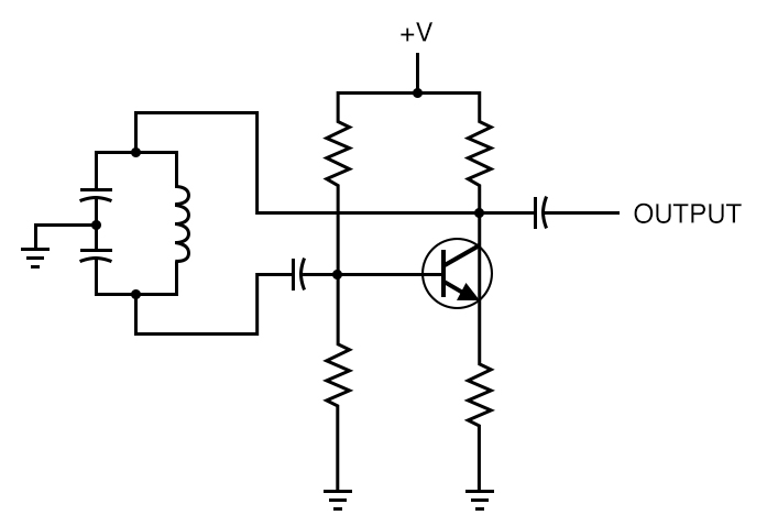
Figure 9. A typical drawing of a Colpitts oscillator
The last two examples introduced a bit of resonance. Because resonant elements depend on the ability of reactive components to supply phase shift, it would be illustrative to talk a little more about phase in resonant circuits.
Modeling Resonant Tanks
A series LC circuit resonates when the reactance of the inductor and the reactance of the capacitor are equal. At this point, the inductor and capacitor share the same current; the inductor ideally provides a +90° (lead) phase shift of voltage, while the capacitor provides an ideal -90° (lag) phase shift of voltage, meaning the voltages at the ends of the circuit are 0° out of phase (no voltage drop, short circuit). A similar effect gives rise to an LC resonant tank.
But as we now know, a capacitor and inductor will only provide +/- 90° phase shift when the source or load impedance is properly set. Take this resonant tank as an example.
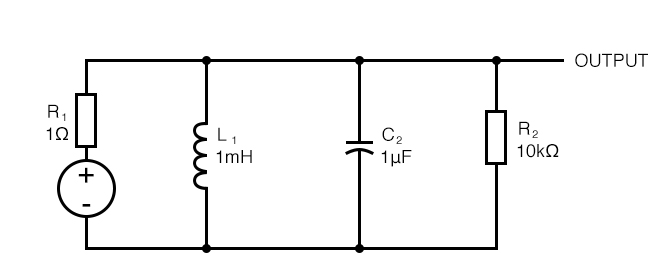
Figure 10. A simple resonant tank, fed by a 1 Ω output impedance. Will it ring?
The source impedance is only 1 Ω, and the load is 10 kΩ. The tank should resonate at 5 kHz. We can test the resonance by applying an input step and looking for ringing. The simulated result is below.
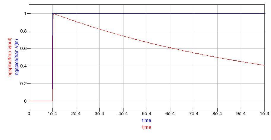
Figure 11. The response of the tank is too damped to allow any ringing, which is desirable in many cases.
The tank doesn’t appear to be ringing too much. The reason lies with the source impedance, which is too low given our values of L and C. We expect our capacitor and inductor to allow an exchange of energy rapidly back-and-forth at the resonant frequency, but the effect is damped because the resonant tank Q factor is too low.
There are a few ways of understanding this. In the context of phase shift, we might propose the following explanation. Looking at the source impedance and the capacitor alone, we see that they form a low-pass RC filter with a cutoff frequency of 160 kHz. Conversely, the source impedance and the inductor form an RL high-pass filter with a cutoff frequency of 160 Hz.
If we agree that a resonant tank’s behavior is dependent on the phase shift supplied by the components (-90° voltage phase shift from the capacitor, +90° voltage phase shift from the inductor), then the reason for damping becomes evident.
The RC low-pass filter will provide -90° phase shift above its cutoff frequency, and the RL high-pass filter will provide a +90° phase shift below its cutoff frequency. The resonant frequency of the tank, 5 kHz, is too high for the RL filter to provide a positive phase shift and too low for the RC filter to provide a negative phase shift.
Reasoning this way, we coax the circuit into ringing by either changing the values of L and C (decreasing inductance and increasing capacitance in equal measure) or changing the source impedance.
Increasing the source impedance has the desired effect.
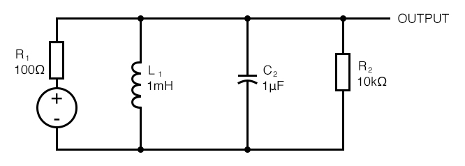
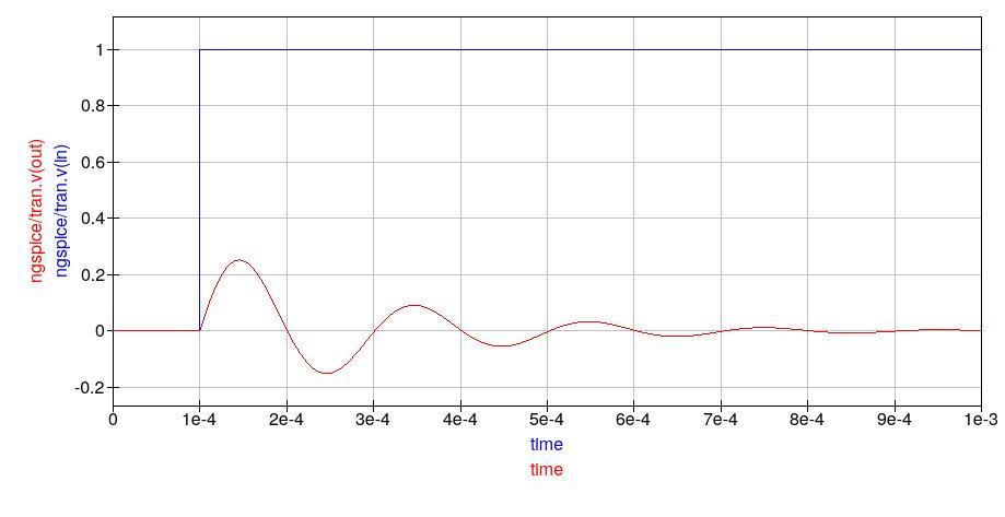
Figure 12. With a source impedance of 100 Ω, the tank rings at 5 kHz.
Now the tank rings, with a period of 0.2 ms (which corresponds to a resonant frequency of 5 kHz), as expected.
Conclusion
This article has taken a closer look at phase shift in analog circuits. Our topic has taken us through a variety of circuits: amplifiers, filters, resonant tanks, and oscillators. Capacitors and inductors can always cause phase shift, but the effect is influenced by the source impedance and the load impedance. Here, we mostly assumed that the source impedance and load impedance are resistive. However, reactive elements are always present.
To analyze reactive elements in a circuit, we should consider the output impedance of the circuit feeding the elements, and the input impedance of the circuit following. Now, when we want a circuit to behave a particular way, we can use our intuition about phase shift to guide us, nudge us in the right direction.
Related Content