Facebook
 Google
 GitHub
 Linkedin
Transformers (Part 1)
Video Lectures created by Tim Feiegenbaum at North Seattle Community College.
We're in Section 7.2 and we're looking at Transformers. Transformers are basic circuit components like resistors and inductors. Transformers are used in nearly every electronic system that operates from AC power so they are widely used. Transformer operation is based on the same principle as inductors. Nearly every computer uses a transformer to step voltage down to lower levels. Just really quickly, if you have a socket plugged into the wall, it goes into a big inductor and it goes through a transformer and it goes through a number of circuits. That's where you end up getting your … eventually you get your 12 volts and your five volts and your 3.5 volts that your computer needs to operate. There's a little bit more circuitry than I've shown here, but ultimately a transformer is the beginning of that process.
Basic Transformer Action
Magnetic coupling is the inductance of voltage from one coil to another. Transformers operate on this basic principle. The percentage of flux that passes from one coil through a second coil is called, this is a term 'coefficient of coupling'. The coefficient of coupling can range from zero to 100, (expressed as a percentage). Usually, it's expressed as a decimal between zero and one.
Transformer Action: Coefficient of Coupling
A voltage is connected to coil L1. Here we have a voltage connected to the coil. What we are looking at here is the coefficient of coupling. Now the voltage connecting here wants to induce a voltage in L2. But if you'll notice, L2 is really outside the range of the flux of L1. The voltmeter here is showing zero volts because it simply isn't close enough. The coefficient of coupling here would be a nice zero. In the lower picture notice the L2 coil is closer to L1 and within the magnetic flux. Therefore, voltage is induced into L2 and it's displayed on the voltmeter. Here the L2 is in much closer proximity to L1 and so we see a voltage.
Now, if the coefficient of coupling was 1, it would indicate a 100% transfer of flux from L1 to L2. Technically that's not possible. For our purposes, we're going to say that the coefficient of coupling is 1 because we're not going to get into … in higher level courses we'll look at what is the actual coefficient of coupling. But for our purposes, it will be 1.
Transformer Terminology
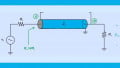
The winding that receives the applied AC voltage is called the 'primary'. Here we have the primary winding. That is what receives the VA here is the applied voltage. The windings that a voltage is induced in a transformer is called the 'secondary winding'. The induction action, magnetic action induces a voltage and you see it in the secondary. The polarity of the voltage in the secondary is dependent upon the direction the secondary winding is wrapped. The phase relationships are indicated in a transformer with 'dot notation' and we're going to look at this on the next slide.
Dot Notation
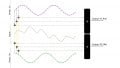
Here we see this, what we call dot notation. What you'll notice here, here we have a transformer and this is the primary, this is the secondary. Notice the two blue dots here are telling us that the phases or the input and the output are in phase and you see the input signal here, see the output and you'll notice that they are in phase. Now, dot notation here is showing us that they are out of phase and so you see here we have AC coming in and here the output is out of phase. This indicates an 1800 phase shift from input to output.
Step Up and Step Down Transformers
Step down transformers are used on many different types of electronic devices that require voltages lower than 120v AC. A common computer operates on 3.5.5 and 12v DC. A transformer steps down the AC from 120v to much lower levels. These voltages are then converted to DC with a device called a rectifier which we will examine in later chapters. There are step up transformers and there are step-down transformers. This … what we're talking about here would be an example of a step-down. In the step-up transformer notice the VOUT is greater than the applied voltages and in the step down the V is less than the applied voltage.
Transformer Types and Applications
There are several ways to categorize transformers. This is classification by application. The first one is audio. These are used to connect audio amplifiers to speakers. Next type is radio. These are used to adjust radio intermediate frequencies (IF). The third is power. They are used to step up or step down voltage. The fourth is isolation. One example of isolation are transformers used in Ethernet systems. The transformer isolates the desired signal from the unwanted noise.
Core Material
They can also be classified by the core material. That is, what is the core of the transformer made of? Now some are what we call Air-core. They're wound around a non-magnetic coil form. It can be plastic, cardboard or any other material with very low permeability. Remember permeability has to do with conductivity. Well, here Air-core you want permeability that's extremely low. Flux that does not cut both primary and secondary is called leakage flux. With Air-core you'll have quite a bit of what we refer to as leakage flux.
Then there are Iron core transformers. They have a highly permeable core generally limited to the audio frequency range. Audio frequency range as a rule of thumb is from 20Hz to about to 20kHz. These are commonly used as power transformers. Then they are the Ferrite-core. These have a high permeability. They are of a ceramic material. They tend to be quite brittle. They're used in the audio frequency range as well as high frequency well up into the Megahertz. Obviously, you're not going to be able to notice this is the audio and Megahertz is millions of cycles. They have low level of leakage flux.
Classification by Winding Connection
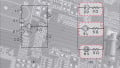
The sketch to the right shows a primary providing several sets of windings for the secondary. Now here we see ... here we have … this is the way that a primary actually looks. Here you have the applied voltage and you have the windings going around the primary core here and then the secondary side here we have windings going around. This would be an applied voltage. There'd be two voltages tapped off of the secondary. Now, if would look at this on a schematic diagram, it would look like this and this would be the primary here and then this would be the two coils tapping off voltage in the secondary.
Okay, Classification by winding connection. Drawings (a) and (b) show transformers where the manufacturer has only one secondary but have used "center taps" so that several different voltages can be and here's the word, "tapped" off the secondary. Here we have a secondary. You'll notice that there are wire connections made to and in some cases several points.
What would happen here is that you could have one voltage off of this and then another voltage could be tapped off here and possibly another voltage tapped here. We could have several voltages tapped off of these – off of one secondary rather than having multiple secondary. This is commonly the way it is done. The manufacturer simply has to go in and connect the center tap to the point where the voltage that he wants to tap off.
Autotransformers
Here and this is … I'm referring to (a), a single tapped winding serves as both the primary and the secondary. A single tapped winding is acting as the primary and the secondary. One end is common for both primary and secondary. We have a common point for primary and secondary.
The output is stepped down from the applied voltage. Here we have a voltage that goes across this entire transformer winding and yet we're only tapping off part of it right here. In this case, the VOUT will be less than the applied voltage. You have a lower value here than you have in your input. In the below circuit (b), the output is across the entire transformer and the input only across a portion of the transformer.
This will be used to step up the voltage. In this case, the center tap can sometimes be moved to adjust the final output. In this case, here we have the applied voltage. Notice that it is connected only to a portion of this transformer. Now, what will happen is that you'll have a flux that is applied here by the voltage and that will be transferred to the rest of this inductor. Now, what will end up happening is that it will result in … from here to here you'll have the applied voltage, but from here up to here we're going to have increasingly larger voltages. This is what we would call a step up transformer. Here the output would be greater than the applied voltage. This is referred to as an autotransformer.
Circuit Analysis of Transformer Circuits
‘Turns ratio' refers to how many turns the secondary coil in a transformer has in relation to the primary windings. You see this term ‘turns ratio' and you see Np/Ns. If you see Np/Ns, what's that referring to is the number of turns in the primary divided by the number of turns in the secondary. If you had 500 to 100, 500/100 then we would say our turns ratio equals five. If the input voltage was 120 volts, then the output would be – in this case, the turns ratio is five, so 120/5 and so our output voltage would be 24 volts. That's addressing the term turns ratio.
Okay. ‘Voltage ratio' refers to the voltage induced in the secondary of a transformer compared to the voltage in the primary. This is the same thing we just looked at here. We said that the Np/Ns and that this would be directly proportional to the Vp/Vs. We just did this. We say 500/100 is the turns ratio. If the voltage is 120 then it would be reflective of the turns ratio. If the turns ratio was 3:1 and input voltage is 120, then the transformer output would be 40.
Okay. The ‘Power ratio' in a transformer is … notice this, is unity. Unity, in this case, means 100%. This means the power in a transformer will equal the power in the secondary. If we have a given circuit here and we have a component over here and we have … say this voltage is stepped down, then the E*I=P.
The power that we have in the secondary will equal the power that we have over here in the primary. Now they're actually some losses but for our purposes, we'll consider it unity. When we do our calculations we will … this will equal this. The reality is that there will be slightly more power in the primary than the secondary because the transfers aren't perfect. But like I say, for our purposes, we will consider that they're in fact unity and actually they are very close to unity.
The current ratio in a transformer is Np/Ns equals… and notice these are reverse. It's going to be the Is/Ip. Our ratio in the transformer is, notice this, unity. Unity to say that the Np/Ns=Is/Ip. Now you notice these are reverse. Here the primary's here. The turns number is in the upper value, but in the current, it's the lower. These two are going to be reversed.
Now let's see how do we reconcile this? Okay, power in the primary is E*I. We know that same thing is … or the power in the product is E*I. That would be true in the primary and the secondary. If voltages step down, then current must increase in the secondary for the power to be equal. The idea here is if we step the voltage down … remember and this being true, then the current has got to go up in order for the power to be equal in both the primary and the secondary.
Here's … if the turns ratio of a transformer is 10 to 1 and the primary has the current of 100ma, what is the secondary current? Let's solve for … let's see. We know … we said the turns ratio is 10 to 1. Primary has 100ma. What is secondary current? Let's solve this equation for current in the secondary right here. What we could do, we want to isolate this, so we could take this side of the equation (Is/Ip)*(Ip) and this side of the equation (Np/Ns)*(Ip). That would cancel this. We could say that the Is would equal the (Np/Ns)*(Ip). Ip, what do we say, the Ip has 100ma of current and then we said it was a 10 to 1 ratio so the Np/Ns of the primary to the second is 10/1. (100)*(10/1), we would have 1000ma. That's the same as 1amp. That is addressing the current ratio in a transformer.
Analysis of Transformer Circuits
Now we're going to look at the ‘Impedance ratio'. Impedance ratio is measured in ohms and because of the relationships between windings, can be altered between primary and secondary windings. The reflected impedance refers to the idea that the impedance in the secondary of a transformer is reflected into the primary. The relationship between turns and impedance is and here we have this particular formula (Np/Ns)=?(Zp/Zs). What we want to do is to solve for the impedance in the primary because usually, we know what the impedance of the secondary is.
Usually, there's a component there, a resistor or something. We know that resistance but we don't necessarily know what the impedance in the primary is. Let's solve this equation for it because what we're saying here is that the Np/Ns=?(Zp/Zs). First of all, we want to remove this square root. Let's square both sides of this equation first of all. If we do that we're going to say that (Np/Ns)2=Zp/Zs. If we want to isolate Zp, we could take (Zp/Zs)*(Zs/1) and (Np/Ns)2*(Zs/1) and this would cancel. We would see that the Zp=(Np/Ns)2*(Zs). If we know what that (Np/Ns) is, we would square that value and then take it times the (Zs).
Okay, we're going this formula and the previous formula in the next session. I'm going to stop this one for now and we will continue on with part (B).