Facebook
 Google
 GitHub
 Linkedin
Capacitors (Part 2) - Current Flow in a Capacitive Circuit
Video Lectures created by Tim Feiegenbaum at North Seattle Community College.
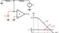
We're continuing in 7.3 on a discussion concluding capacitors. We're looking at current flow in a capacitive circuit. Even though a capacitor has an internal insulator, and that's going to be right here, current can flow through the external circuit as long as the capacitor is charging and discharging, so as long as it's charging and discharging current can flow. You may recall that in the previous discussion we had our capacitor connected to a DC source. With DC, remember current is only going in one direction, so once the capacitor was charged then current ceased to move in that circuit at all. It opposed the source and there was no movement.
With AC, it's a little bit different because with AC we had a signal that going positive and then it's going negative, and so what will happen is when the circuit goes positive the charge on the capacitor will be a positive charge. When the AC signal goes in the negative direction the capacitor will discharge, and then it will charge it with the opposite polarity, and so the capacitor will be constantly charging and discharging so current will continue to move in the external circuit with an AC signal source. Remember that current does not go through the cap.
Another point of discussion concerning the movement of current, an open circuit form and accidental capacitances that charge to the value of the applied voltage. Now you may recall when we looked at DC circuits. We looked at DC circuits and you may recall that we connected components up and I'm going to put in a few resistors here. One of the things that we found was that when we had an open circuit, I purposely didn't connect this, when we had an open circuit and we went in here with our volt meter and we connected across the two points of our open, we found that we had the supply voltage was felt right here. One of the reasons that we had that was that remember that we had to have a complete circuit for current to flow. When there was no voltage drop across these components then there was no current flowing through, then there was no voltage drop, and so when we measured here we felt the supply voltage.
Another way to look at that is this is an accidental capacitance because here remember that air can operate as a capacitor. The end of the wire is going to be an extremely small plate area, but you can do this as an accidental capacitance and then you see the applied voltage. The thing is that when you take the voltage away this capacitor is not going to hold it very long just because the plate area is so small and the distance between the plates is probably so large, but at any rate, this can be viewed as an accidental capacitance.
Capacitive Reactants
The value of current in a capacitive circuit with an AC source is directly proportional to the value of the capacitor. Current is also directly proportional to frequency, meaning the cap has to charge more times per second. Opposition to current flow due to the charging and discharging of the plates is referred to as capacitive reactance and it is calculated like this: One over two, pi, times frequency, times capacitance. This value like with inductive reactance is measured in ohms, only thing is that remember when we calculated inductive reactance, remember X of L, we said we had two pi times frequency times inductance. In this case, we have this very similar format except it's one over that value and we replace C with L. At any rate, they both represent opposition to current and they are measured in ohms.
Capacitive reactance. Here's our formula again. We're going to calculate what the capacitive reactance offered to a 20 microfarad cap when in a 60 Hz circuit and then in 200 Hz circuit. Here we have our formula. Here, we're calculating with 60 Hz and we result with a 132.6 ohms. We increase the frequency and notice what happens to the resistance that it actually goes down. If we had been dealing with an inductance it would've gone up, the higher frequency the more reactants. In this case the higher frequency the lower the reactance. You can see that when F is in the denominator, the higher F goes the lower the reactance. Notice like inductive reactance, capacitive reactance is a function of frequency, but they are inverses of each other. With inductive reactance, as frequency goes up, reactance goes up, but with capacitors, as frequency goes up reactance goes down.
Capacitor Types
There are many ways to categorize capacitors and distinguish between them. We're going to categorize them with three different methods, by the lead style, fixed and variable, and polarized and non-polarized. For these first two, I do want you to take a look at your book. Lead styles, they're nice pictures there of aerial, radio, and the different lead styles. Sometimes you see them like this, and sometimes you see them like this, and sometimes they're surfaced mounted, but please refer to your text for some pictures.
Then, there are fixed and variable. This just has to do with resistors and inductors. Capacitors can be of a fixed value or they can be variable. Again, please see your text for some pictures of those.
Then, we have polarized and non-polarized capacitors. Polarized capacitors must be inserted into the circuit according to the polarity marked on the capacitors. Usually, you'll see a plus or a minus on the capacitor if it is of the polarized type. In placing the circuit incorrectly they can and do explode, so great caution should be exercised when placing polarized caps in the circuit. I have seen many of these explode, kind of embarrassing for the person putting in the circuit in the lab. They go in there and they blow up. Everybody thinks, oh my, a capacitor in backward, so oftentimes people learn this, but there is a hazard involved so ensure that when you put them in the circuit that you're putting them in correctly. Non-polarized capacitors can be placed in a circuit in either direction, so non-polarized don't care, but the polarized variety you must use caution.
Capacitor Ratings
Capacitors are rated according to three features, and we're going to be looking at capacitance, voltage, and temperature coefficient. The first is capacitance, and this is where you would see where it's rated as 400 microfarads or I don't know 0.1 microfarads or whatever. They also have an associated tolerance like with resistors you might see 5% or whatever. They have a variety of tolerances associated with them.
Voltage indicates the maximum voltage that can be applied to the capacitor without damaging the circuit. Oftentimes, you'll see, for example, 100 or 250 or 400, just a few of the values you might see.
Then, there is the temperature coefficient. This addresses how the value of the capacitor will change under the influence of heat. It addresses polarity and magnitude. This addresses how the value of the capacitor is going to change under the influence of heat. Two things we're going to look at, polarity and magnitude. Polarity has to do with does the capacitance go up or does it go down with the influence of heat because different types of capacitors can go either way. Then, the magnitude, it tells how much the capacitance value changes for a given temperature. This is given in parts per million per degree Centigrade. Temperature coefficient information is provided by manufacturer data sheets and usually not written on the capacitor.
Capacitor Technologies
In this particular section, I'm not going to lecture. I want this to refer you to your text because your text has some nice pictures associated with different capacitor technologies, so please do read that section from your textbook.
Related Content