Facebook
 Google
 GitHub
 Linkedin
Inductors (Part 2) - Types and Applications
Video Lectures created by Tim Feiegenbaum at North Seattle Community College.
We're continuing in section 7.1, and we're looking at inductor types and applications. All inductors are similar in certain respects. They all possess inductances, self-induced voltages, and oppose changes in current. These are these three common characteristics of all inductors. They possess inductances, they have a self-induced voltage, and they oppose changes in current.
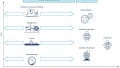
Inductors can be classed by either fixed or adjustable. Over here, we see the schematic symbol. Here we have a fixed inductor and here we have an adjustable conductor. The core materials used include iron, powdered iron, and ferrite. Ferrite bead, and there's a picture of some of these in your text, are used to add inductance and resistance. They have a wide variety of sizes and shapes. Ferrite components typically have a hole through which a wire or leaded component may be inserted. They add series inductance and resistance to a wire, and notice this, at high frequencies. This is wherein the first section we had mentioned how they could be used to choke out unwanted high frequencies. This is one application where that will happen.
Ferrite Beads
One of the more common uses of ferrite beads is with computer cables where they are slipped over the cable while the cable is being made or snapped around the cable in two pieces after the cable has been manufactured. These are seen in mice, keyboard, and monitor cables. Cables can act as antennas interfering with radio and television audio and video. They can also receive signals that can interfere with computer operation. Here we see this is a cable from a computer monitor. You notice this is the end that would plug into the computer. Here we have our ferrite beads. These will be used to attenuate and remove high frequencies coming out of the computer or those might accumulate through the cable since the cable can act as an antenna. Ferrite beads work by reducing the radio frequency interface created by these cables. The interference can come from a couple of different sources that at any rate the ferrite beads are used to reduce these high-frequency signals.
Series and Parallel Inductors
Inductors may be connected together like resistors. With inductors, inductance and inductive reactance must be considered. Here we have a circuit. This looks much like the circuits we considered earlier with resistors where we had resistors in series, and here we have inductors in series.
Series inductors combine, notice the note here, like series resistors. If we had given inductances here they add up just like we would with resistance. Let's say this one is 100 mH and maybe this one is 200 mH and maybe this one is 300 mH. If we were to add these up there would be 600 mH of inductance in this circuit. Series inductive reactances can be found by summing the individual reactances. Here we have the individual inductances, but we do not know what the reactances are and we wouldn't be able to do that unless we knew what the frequency of our signal source was.
Remember, we did this earlier. We said that the inductive reactance was equal two times pi times the frequency which were not given here. In this case, if it was L1 here, times 100 mH and that would give us an X of L value in ohms. We could do it for 200 and 300. We could calculate the inductive reactance of each, and then we would add them up to get the total reactance. Probably the easier way to do this or the sensible quick way to do it would be to say that X of L equals two times 3.14, which is pi, times whatever the frequency is, and then multiply that simply times the total inductance of the circuit and that would give us our total reactance in ohms. These would add just like they would in a series resistance circuit.
Parallel Inductances
Parallel-connected inductances divide the current flowing into them. You have a source of current here and the current is going to go through this is going to be divided from the source. The induced voltage for a given inductor will be lower for each of the individual inductors when compared to the applied current. Total inductance in a parallel configuration is found by: Here we're calculating what is the inductance in this entire circuit. This is, remember, the one we looked at was series prior to this, this one in parallel. If we were just to put some values here, let's just say that we're going to put in the same, not 3,000, 300. We'll say 100, 200, and 300 is the inductance of each of these inductors. If we did this formula here, if you look at this formula, this looks very much like the formula that we used in calculating parallel resistance. I don't know if you recall, but in parallel resistance, we found that the parallel resistance was going to be less than the smallest component. If we were to go ahead and solve for this we would find and if we were, I guess we could just draw it right here if we were to sum the inductance of all three of these we would find that it would be less than 100.
Parallel Inductive Reactances
When inductive reactances are connected in parallel the total inductive reactance is less than the smallest individual reactance. This is the same thing that we just looked at when we were looking at inductance, only now we're looking at the inductive reactance. The parallel inductive reactance is calculated with this formula. Again, this is the same formula that we used with resistance. If we were simply to change this to R, R, R, and R, this would be the same formula. This is very, very similar in another regard when the formula is the same, and actually, the values we're looking at are very closely related. Because remember we looked at resistance it was measured in ohms and the inductance here, remember these reactances they are also measured in ohms. It's just that the reactance is going to be a function of frequency. This then in inductive circumstances this frequency can vary based on the frequency, but the formula to calculate the reactance which is measured in ohms is exactly the same formula.
Parallel Inductance Circuit
Here we have a circuit. This is a circuit you could build in Workbench. In fact, I did build this circuit in Workbench. I copied it and pasted it here. What I'd like to do is just to do a few calculations here. We'll calculate the parallel inductance, and then we'll calculate the reactance in this as a whole circuit. Let's bring up our little calculator. First of all, we'll calculate the parallel inductance. Remember, this is the same formula that we used for resistance, 100 milli, that is the same as 0.1. We'll come down here and we'll say 0.1, and then we'll do the one over function, and we'll add that to and here we have 0.2, 0.2 and again, one over, and then plus 0.3, 0.3 and one over, and then that will equal 18.33. Then, we'll do the one over function here. Here we have the inductance. This is the parallel inductance, so you'll notice that the parallel inductance is less than the smallest component.
We have, let's just round that to 54.5, and we'll note that 54.5 mH. We could redraw this circuit. We could say here is our signal source and we have an inductance of 55.4, and this is a one-volt source at one KHz. If we were going to calculate the reactance of this circuit, then we would say, let's see, we'd start with two times 3.14, which is pi, times the frequency which is 1,000, one KHz, times the inductance which is 54.5 mH. Let's get the calculator and see what we would get there. We would say two times 3.14 times the frequency of 1,000 times 54.5 mH, 54.5, let's see exponent minus three equals and we get 342.2 ohms, 342 ohms. That is going to be our value that we'll call X of L. That represents the total reactance of the circuit.
How could we check that to see if that is, in fact, the correct answer? When I did the simulation with this circuit, notice I inserted the meter into the circuit and I measured the current. I just typed in the value which was 2.917 milliamps. Because an inductor acts much like a resistor in regard to its resistance, we could use Ohm's Law to verify that this is, in fact, the correct answer. We could use any area because we know the voltage, we know the current, we know the reason. We could've used any variation of Ohm's Law to do that. If we say voltage divided by resistance should equal current. Our voltage is one, our resistance is 342, let's see what we get. Let's get our calculator out here and we'll say one volt divided by 342 and that should equal 2.92. That is very close to our value over here. That confirms that our answer is in fact correct.
Circuit Analysis of Inductive Circuits
Solving for voltages and currents in an inductive circuit uses the same principles as for resistive circuits using variations on Ohm's Law. I just mentioned them on the previous slide, but these are the formulas for Ohm's Law. The only difference is that where the X of L here would be R. Remember, current equals voltage divided by X of L. That is the same thing as current equals voltage divided by resistance, which we've done before. Voltage equals, in this case, current divided by X of L or current times X of L, some of the hat would current times resistance in Ohm's Law. Then, here we have X of L equals VL over IL and in Ohm's Law that would be resistance equals voltage divided by current.
We're going to complete this session with looking at calculating the voltage drop across an inductor. There are a couple of ways that we could do this. Here, again, this is another circuit from Electronics Workbench. We have 500 mV RMS applied at a frequency of 200 kHz. We have inductors in the circuit. I already went in and calculated the reactances. This 250 at this particular frequency is going to be 314 ohms. This 100 mH component will be at 125.6 given this frequency. Given this, we can apply basic voltage divider rules that we did with resistors. We could say like we've done right here, 125.6 divided by 125.6 plus 314. That would give us a ratio times the 0.5 volts which are the applied voltage and that would give us 142.8 mV.
Another way, the inductances are also proportional. We could've just said 100 mH over 100 plus 250 times 0.5, and we would've gotten the same value because this would yield the same ratio as this, and we would've gotten the same answer.
This has been a look at inductances in circuits. This is a series circuit, and then we looked at how the same principles that apply to Ohm's Law will apply to inductance, especially inductive reactance. Then, we did some calculations with parallel inductance and we calculated the reactance in the circuit. We looked at parallel reactances, parallel inductances, and inductance in series. We talked about ferrite beads. Your text doesn't go into the details that I mentioned here, but I wanted to bring this up simply because this is a common application where you'll see the use of ferrite beads.
Related Content