Facebook
 Google
 GitHub
 Linkedin
RC Time Constants (Part 1) - Pulse Circuit Response
Video Lectures created by Tim Feiegenbaum at North Seattle Community College.
We are in section 7-4, and we're continuing with pulse circuit response.
Pulse Circuit Response
Pulse circuit response is important to understand in digital applications as these tend to use pulsed or rectangular waveforms. The waveshapes associated with sinusoidal waveforms is much different from that of rectangular. What we looked at in previous sections was we were considering a sinusoidal waveform looks like this. Now we're going to be looking a waveform that would look more like this, a rectangular or a square wave. Sometimes we call them pulsed.
RC Time Constants
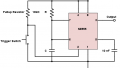
RC time constants define the time it takes for a capacitor to charge. In the circuit below, we are charging the cap with a changing DC source which effectively is a notice, a rectangular wave. Here, we have a circuit. We're applying a 12 volt DC source. Notice, it's not sinusoidal. Here, we have a switch. When the switch is in this position, the cap is charging and there's going to be, there's going to be a time associated with how long it takes this capacitor to charge, and then when the switch goes into this position like it is over here, this is the same circuit, it when it goes into this position now the applied voltage stops and now the capacitor is discharging. Effectively, applying a voltage gives us our high and our square wave, and then when the switch closes we have this. This would be indicating our square wave input.
For a given capsize, it will take a certain amount of time for electrons to accumulate on the plates of the cap and fully charge dependent upon the size of the cap and the charging current through the resistors. In this particular case, here we have a voltage applied. There is a resistance here. This will allow a certain amount of current to flow, and then it will cause this capacitor to charge.
The electrons are going to be flowing as such. They will charge this capacitor and the polarity on the cap will be as such. Again, depending on how long the voltage is applied and much current is flow will affect how long it takes for this capacitor to actually charge. Dependent upon the size of the cap and the charging current through the resistor, the size of the resistor will greatly influence the time of the cap to charge. The size of this resistor has a great deal to do with how long it will take this capacitor to charge.
Let's continue with this discussion. Again, this is the same circuit here, the value of charging current decays as the cap charges. Again, here we have the voltage applied, and here we'd have a minus here, we'd have a positive here. As this switch is closed, current is flowing and this capacitor is charging. Now you'll notice here is that this capacitor is going to act much like a battery. You'll notice that the positive terminal is here, the negative terminal is here, and the charging of this cap is going to oppose this charging voltage. When this capacitor is fully charged what will happen is that this will completely oppose this and effectively no current will be flowing. What this is saying the value of charging current decays. It decays as the cap charges. Initially, as this switch is closed like this there's a lot of current that is charging this cap, but as this cap reaches its full charge point than current decreases and there is effectively no current flow. The charge in the cap will oppose the DC source.
Recall when the cap is fully charged, current will cease to flow. The time required for the cap to charge is divided into five periods and called time constants. We're going to be looking at it on the next two screens. Before we go there, though, let's take a look at this particular schematic. Notice when the switch is closed, now the voltage is no longer so the applied voltage you'd have something like this. At this point, we've got no voltage applied. In this case, the circuit is closed and now there is a discharge path for the capacitor. Now notice something, that in this case, the current path was like this as it was charging in this direction, but when this switch is closed notice it's a negative deposit. The current is going to reverse and it's going to flow in the other direction until this capacitor charges, and then if we close the switch again then it would recharge again.
Time constants. The Greek letter tau is used to represent one time constant. Here we have tau equals and notice R times C. The formula above is used to calculate time constants and this is in relation to how long it takes for the capacitor charge which we had looked at in the previous screen.
Here we have a graph. The diagram below shows the cap charging in comparison to charging current. Notice, what are we looking at here? Here we have the line going up here, and this is a capacitor and we are charging the capacitor. This is the voltage and this is current related to this charge. These letters down here, these represent the time constants tau which we just mentioned on the previous slide.
After one time constant, the cap is charged to 63.2% of the applied voltage and the charging current has decreased to 36.8%, so what does this mean? Here at 100% what we're looking at, this is the applied voltage but it is also the applied current. This would have to do with the size of the resistor that we were looking at previously. Here we have initially when that switch is closed we have massive current flowing through the, I shouldn't say massive, but we have a lot of current flowing through the resistor and the capacitor is beginning to charge. What we'll notice is that the voltage on the cap will be 63.2% of the applied voltage. This is the first time constant. This would time constant one, if you will, right here. You'll notice that the charging current has decayed to 36.8% of its original value.
During the next time constant the cap will charge an additional 63.2% of the remaining voltage and the current will decrease likewise. What does that mean? Here we're at 63.2% of the applied voltage and now the difference between 63.2% is a given value and this cap will charge to 63.2% of that value, what is leftover between here and the applied value. It will continue to do this through five time constants and the current will be decreasing at the same ration.
Now after five constants, the cap will be at 99% of its value and the current will decrease to less than 1% of its initial value. This is much like we looked in that previous circuit where the capacitor was charging and when it reached its full charge it was opposing the applied voltage and current ceased to flow.
The below chart illustrates the capacitor current and voltage during discharge. In this particular screen, we are looking at the voltage and current during charging. Now we're looking at the voltage and current during the discharge. You'll notice here the VC and I are going to be proportional. In this case, this would be the capacitor where the switch is now in the position where the cap can discharge through the resistor and the voltage and current will directly proportional because now the capacitor is in effect the battery and it is providing all of the voltage and current for the circuit. They will decrease and you'll notice here in during time constant one the voltage will decrease by 63.2% of its value. Notice up here we're saying that time zero is at 100% it begins to discharge, at time it's down to 63.8% and it will continue to decrease by 63 of the remaining voltage until the five time constants have elapsed. This, again, is going to be the same relationship as we saw in charging only now the voltage and current are deteriorating and is going to be in relationship to the same time constants that it charged by.
Solve
RC time constant for the below circuit. Here we have a circuit and let's find our little calculator, and let's do a little bit of calculating here. First of all, here we have the applied voltage, 100 volts. Here we have a switch, and here we have a resistor and a capacitor. Now our calculation for the time constant is going to be R times C. Let's go over here and our R value is 2.2 megs, so 2.2 exponent six times the value of 500 and this would be exponent minus six and that will equal. We have a value here to 1,100, so we're saying 1,100 what? Those are seconds. Let's divide that by 60 and we'll say ok. This actually has a charging time of 18 and third minutes. If we were to close this switch it would take 18.3 minutes for this cap to charge. Now, this is a fairly long charge time, but that is greatly impacted by the size of this. If this was a much smaller resistor that charge time would be greatly reduced. If we're looking at the support to be fully charge, it would be five times this value. If we took that times five we'd be looking at an hour and a half for this to be fully charged, and again, an hour and a half for it to be fully discharged.
Our RL time constants, we're not going to spend any time with these, but I'm just going to mention them. The RL circuits also have a time constant computed thusly and here we're going to have tau equals L, now notice it's L divided by R. In our RC, it was R times C, and so the tau here would be probably pretty small, though, because inductance is typically a value less than one and our resistance if it's 1,000 or a million or whatever, we're going to find that the time constant will be very short.
In this section, we looked at time constants, we solved for a time constant in this particular circuit. We looked at the discharge time and they were based on time constants. We looked at the charge time based on time constants. Remember that the voltage and current were inversely proportional during charge and they were directly proportional during discharge. Here is tau. Remember, this was, in this particular section, we're looking at time constants and we're relating them directly to a rectangular wave via the sinusoidal way that we had looked at in the previous sections.
Related Content