 Facebook
 Google
 GitHub
 Linkedin
Practical Considerations - Capacitors
Capacitors, like all electrical components, have limitations that must be respected for the sake of reliability and proper circuit operation.
Capacitor Working Voltage
Working voltage: Since capacitors are nothing more than two conductors separated by an insulator (the dielectric), you must pay attention to the maximum voltage allowed across it. If too much voltage is applied, the “breakdown” rating of the dielectric material may be exceeded, resulting in the capacitor internally short-circuiting.
Capacitor Polarity
Polarity: Some capacitors are manufactured so they can only tolerate applied voltage in one polarity but not the other. This is due to their construction: the dielectric is a microscopically thin layer of insulation deposited on one of the plates by a DC voltage during manufacture. These are called electrolytic capacitors, and their polarity is clearly marked.

Reversing voltage polarity to an electrolytic capacitor may result in the destruction of that super-thin dielectric layer, thus ruining the device. However, the thinness of that dielectric permits extremely high values of capacitance in relatively small package size. For the same reason, electrolytic capacitors tend to be low in voltage rating as compared with other types of a capacitor construction.
Capacitor Equivalent Circuit
Equivalent circuit: Since the plates in a capacitor have some resistance, and since no dielectric is a perfect insulator, there is no such thing as a “perfect” capacitor. In real life, a capacitor has both a series resistance and a parallel (leakage) resistance interacting with its purely capacitive characteristics:
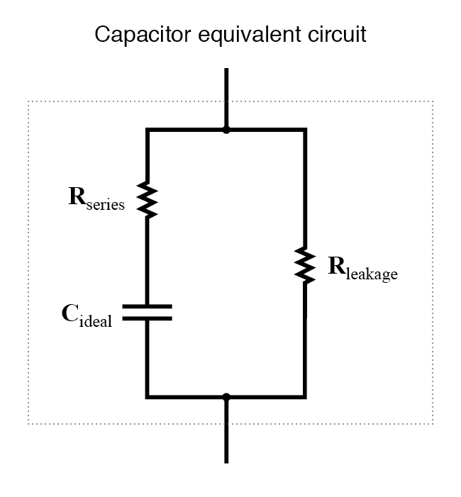
Fortunately, it is relatively easy to manufacture capacitors with very small series resistances and very high leakage resistances!
Capacitor Physical Size
For most applications in electronics, the minimum size is the goal for component engineering. The smaller components can be made, the more circuitry can be built into a smaller package, and usually, weight is saved as well. With capacitors, there are two major limiting factors to the minimum size of a unit: working voltage and capacitance. And these two factors tend to be in opposition to each other. For any given choice in dielectric materials, the only way to increase the voltage rating of a capacitor is to increase the thickness of the dielectric. However, as we have seen, this has the effect of decreasing capacitance. Capacitance can be brought back up by increasing the plate area. but this makes for a larger unit. This is why you cannot judge a capacitor’s rating in Farads simply by size. A capacitor of any given size may be relatively high in capacitance and low in working voltage, vice versa, or some compromise between the two extremes. Take the following two photographs for example:

This is a fairly large capacitor in physical size, but it has quite a low capacitance value: only 2 µF. However, its working voltage is quite high: 2000 volts! If this capacitor were re-engineered to have a thinner layer of dielectric between its plates, at least a hundredfold increase in capacitance might be achievable, but at a cost of significantly lowering its working voltage. Compare the above photograph with the one below. The capacitor shown in the lower picture is an electrolytic unit, similar in size to the one above, but with very different values of capacitance and working voltage:

The thinner dielectric layer gives it a much greater capacitance (20,000 µF) and a drastically reduced working voltage (35 volts continuous, 45 volts intermittent).
Here are some samples of different capacitor types, all smaller than the units shown previously:


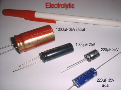

The electrolytic and tantalum capacitors are polarized (polarity sensitive), and are always labeled as such. The electrolytic units have their negative (-) leads distinguished by arrow symbols on their cases. Some polarized capacitors have their polarity designated by marking the positive terminal. The large, 20,000 µF electrolytic unit shown in the upright position has its positive (+) terminal labeled with a “plus” mark. Ceramic, mylar, plastic film, and air capacitors do not have polarity markings, because those types are nonpolarized (they are not polarity sensitive).
Capacitors are very common components in electronic circuits. Take a close look at the following photograph—every component marked with a “C” designation on the printed circuit board is a capacitor:

Some of the capacitors shown on this circuit board are standard electrolytic: C30 (top of board, center) and C36 (left side, 1/3 from the top). Some others are a special kind of electrolytic capacitor called tantalum, because this is the type of metal used to make the plates. Tantalum capacitors have relatively high capacitance for their physical size. The following capacitors on the circuit board shown above are tantalum: C14 (just to the lower-left of C30), C19 (directly below R10, which is below C30), C24 (lower-left corner of board), and C22 (lower-right).
Examples of even smaller capacitors can be seen in this photograph:

The capacitors on this circuit board are “surface mount devices” as are all the resistors, for reasons of saving space. Following component labeling convention, the capacitors can be identified by labels beginning with the letter “C”.
RELATED WORKSHEETS:


Thank you for the detailed articles.
I need one help to understand clearly through my exploded capacitor having the following information please
Loge ejc
Tesla, 9.151(x) +2x0.0025 uF IY
+/-20%Frez=2 MHZ
250V 10A
This one from old vacuum cleaner.
What capacitor is this and what is 2 MHZ