Facebook
 Google
 GitHub
 Linkedin
Troubleshooting Semiconductors
Video Lectures created by Tim Feiegenbaum at North Seattle Community College.
We're in the final section of our introduction to semiconductors. We're going to take a brief look at troubleshooting them.
Mechanical considerations
Leads should be bent with needle-nose pliers. Some semiconductors have glass packages and need to be handled with care. Repetitious bending of the lead can cause them to break. Over here there are some pictures of right and wrong ways to do things. Here we have a very sharp bend. When you have a very sharp bend you run the risk of weakening the wire connection. You could actually break it if you bend it too many times. The gradual bend is much better. Here we have a bend that is really too close to the package. It may damage the package. It's much better to have something like this so that you don't risk damaging the package. Like I said, often these are ceramic and you could break them quite easily.
Soldering and De-Soldering
Troubleshooting often requires the component to be soldered or de-soldered into or from the circuit board. Semiconductor devices are temperature sensitive and caution should be used in soldering and de-soldering. They are temperature sensitive and the soldering iron is hot and you don't want to destroy the conductor when you're putting it into the circuit. Heat sinking solid state devices are essential to protect them from thermal damage. Heat sink, your text has a picture of a technician using a pair of pliers as a heat sink when soldering the lead of a semiconductor. The pliers are between the semiconductor and the soldering iron, so hopefully, they will absorb the heat.
Electrical Considerations
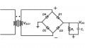
Junction voltage measurements are useful in troubleshooting semiconductor devices. A forward biased junction will have approximately 0.7 volts across it if germanium it will be about 0.3. An ohmmeter can be used to test a PN junction. One of the ways you can do this is to measure the resistance across the PN junction. A front-to-back ratio of at least 1:10 should be the result of an ohmmeter test. What this means, if you put the leads of the ohmmeter across the PN junction and you have it set to read ohms the forward bias condition should be quite small and the reverse bias condition should be at least 10 times that value. Some ohmmeters also have a special connection for testing PN junctions. When we measure across them it will read 0.7 volts in the forward biased connection and infinity in the reverse bias.
That completes part about troubleshooting. We looked at electrical conditions, soldering, and de-soldering, and then we looked at briefly at connecting them into the circuit.
Related Content