Facebook
 Google
 GitHub
 Linkedin
Diode Characteristics - Diode and Diode Circuits
Video Lectures created by Tim Feiegenbaum at North Seattle Community College.
We're in chapter nine and in chapter nine we'll be looking at diodes and diode circuits. Diodes are the first application that we will look at addressing the use of semi-conductors. The first thing we want to do is look at diode characteristics.
Diode Characteristics
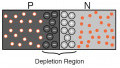
A diode is simply a PN junction, but its applications are extensive in electronic circuits. Three important characteristics of a diode are, first of all, the forward voltage drop. Under a forward bias condition, this should be about .7 volts. Then there is the reverse voltage drop. In the reverse, when we reverse bias the diode the depletion layer widens and usually, the applied voltages are felt across the diode. Then there is the reverse breakdown voltage. Reverse voltage drop that will reverse current flow and in most cases destroy the diode.
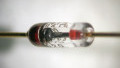
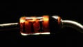
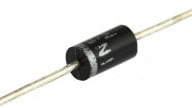
Diode Elements
A diode has two leads connected to the external circuit. Here we have a little diode here and this would be the two leads. Since the diode behaves differently depending upon forward or reverse bias it is critical to be able to distinguish the leads. The anode connects to the p-type material, this would be the anode right here, this connects to the p material. The cathode connects to the n-type material right here. When you see a diode there is usually a colored band on the diode and the color band indicates the end that is the cathode. One way to remember the designation here is that the arrow always points to the end material. The p material would be here and the arrow was pointing at the end material, which would be the cathode.
Ideal Diodes
In an ideal diode, current flows freely through the device when forward bias, having no resistance. This is ideally what should happen, or what we would want to happen, but this is not what will happen. In an ideal diode, there would be no voltage drop across it when forward biased. All of the source voltages would be dropped across circuit resistors. There'd be no voltage drop across the diode; all of the source voltage would be applied across circuit resistors. In an ideal diode, when reversed bias, it would have infinite resistance, causing zero current flow.
Practical Diodes
Now practical diodes, this is what you'll actually see, a practical diode does offer some resistance to current flow when forward bias. Since there is some resistance there will be some power dissipated when current flows through a forward bias diode. Therefore, there is a practical limit to the amount of current a diode can conduct without damage.
A reverse bias diode has very high resistance. Excessive reverse bias can cause the diode to conduct.
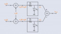
Practical Diode Forward Bias
Here we have a situation; the applied voltage is less than .7 volts. Now remember to forward bias a diode we had to place more than .7 volts across, with less than .7 volts we won't be able to overcome the barrier potential and this will act like an open and there will be no voltage dropped in the circuit. Here we have the same thing only we've increased the voltage to five volts and now there's enough o forward bias this diode. Notice .7 is dropped here, the remaining voltage is dropped here, the 4.3, so this is our 4.3 plus seven equates to our five volts. If this was a 1k component here then 4.3 divided by 1k, we'd have 4.3 milliamps of current through this resistor and through the diode. In this case, we have increased the voltage to 25 volts. Now notice that the voltage drop shown here is .8 volts, ideally, we would say that it is .7. In this case, again if it was 1k then we would have what, 24.2 milliamps of current in this circuit. There is some internal resistance in the diode so as currents increase you will see the voltage drop increase a little bit, but usually, we say that it is .7.
Now in some cases, I've seen rectified diodes where the voltage drop is as high as one volt, sometimes it's as high as maybe 1.2. This is unusual; usually, we consider it to be .7 volts.
Reverse Bias
Now here we have the diode end in so that it is reverse bias. Notice that the cathode is connected to the positive supply. Remember that n material here with all the electrons is going to be attracted this way and we're going to increase that depletion region and the capacitor and the diode so it looks an open. The 10 volts will be felt across the diode and this is a reverse bias condition. This situation we have simply increased the voltage. The same condition exists except the depletion region is probably a little bit wider and the applied voltage is felt across here and there is no current in the circuit.
Exceed Breakdown Voltage
Now here the applied voltage is greater than the breakdown voltage. We don't know what the breakdown voltage of this diode is, but it is greater than that. What's going to happen at this point is, even though it is reverse bias, current will be forced to flow through this device. The device is effectively breaking down and was going to have the current through here will be the applied voltage minus whatever drop there is across this device. This usually damages the diode.
Current Versus Voltage
In a practical diode, there is very little forward current until the barrier voltage is reached. When reverse bias only a small amount of current flows as long as the reverse voltage is less than the breakdown voltage of the device. What we have, we have a current versus voltage curve for a practical diode. This is pretty generic in regard to diodes. You see all basic diodes look like this. There are some other diodes, special application diodes would be a little different than this, but this is the curve that you generally see in a diode. The value that will vary will be this one here, the breakdown volt. What does this mean? Well, here we have the knee voltage, the barrier voltage, and the knee voltage … Remember here we're graphing voltage going this way. This would be voltage forward and then this would be reverse voltage indicating reverse bias. Voltage in forward bias condition would typically be .7 volts and then we're graphing current, going this way. Now you see that this curve it's not straight up, it has a gradual curve to it. .7 volts to diode begins to conduct and then we began to have what we'll call forward current.
As the voltage goes up, I think we graphed five volts and we'd probably have a current about here and then we did 25 volts and we said that we had about .8 volts, but you get the idea if we grabbed this and came down here we'd see, this would probably be about .8 in that particular case. At any rate, the forward voltage is typically .7 and then based on how much current is flowing through it, you might see a slightly elevated value about .7. Now, when we reverse bias the diode you'll see that the current flow is virtually zero and ideally it would be zero, but there is going to be a little bit of leak. You've got, for the most part; we're looking at no current flow at all. In reverse bias, we would see this condition until we reached the breakdown point. The breakdown point we're going to see a rush of current going in the other direction against the normal current path of the diode and again this probably represents the destruction of the diode.
This concludes our introduction to diode characteristics and we looked at this last slide that we looked at was the current versus diode voltage curve for current and voltage. We also looked at the breakdown voltage and we looked at a couple of different reverse bias conditions, as well as some forward bias conditions. We talked about the, let's see where was it, we talked about practical diodes, ideal diodes … oh, here it is. We looked at the diode elements and that concludes our look at diode characteristics.