Facebook
 Google
 GitHub
 Linkedin
Special Diodes - Varactor Diodes
Video Lectures created by Tim Feiegenbaum at North Seattle Community College.
We're continuing in section 9.4 with a discussion about special purpose diodes. And we're looking, now, at a device called a Varactor diode. Junction capacitance is present in all reverse biased diodes because of the depletion region. And you may recall that when we looked at a diode we have the n-type material and the p-type material. And where they met we have this area … in fact, when it was reverse biased we had a voltage across this. And when reverse bias there … the depletion region form here.
This depletion region is an area void of carriers. And since there are two pieces of material here and it is an open circuit, there is a voltage across it, there's going to be a capacitance related to this junction. Now junction capacitance is optimized in a Varactor diode and is used for high frequencies and switching applications. And you'll note here in the diagrams that are used to define this device, here we have a diode and here's a capacitor and there's an arrow indicating that it is variable. Here we have a diode and a capacitor. Again, here is a diode and a capacitor. And down here I think I'll draw a little line here just to let us know that this is a Varactor in the circuit here.
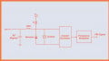
Varactor diodes are often used for electronic tuning applications in FM radios and in televisions. They are also called voltage-variable capacitance diodes. And the value can vary from two picofarads to more than a thousand picofarads. And so here we have a tunable tank circuit. And this is typically the way that this would be used. Notice I have a power supply here and it is reverse biasing the Varactor. And usually this would be a variable and this would be the mechanism that we would use for tuning. And as the voltage is varied here the capacitance across the Varactor is going to vary. So this device … it is used in reverse bias condition and it is used as a variable capacitance and it is optimized, again, for high frequencies and junction capacitance.
Schottky Diodes
Then we have a Schottky diode. And this is the schematic symbol for a Schottky diode. While Varactor diodes are designed to optimize the effect of junction capacitance. Schottky diodes are designed to minimize the junction capacitance. The junction is made of gold or aluminum and n-type silicon. So you notice the p-type material is taken away and it's replaced with either gold or aluminum. This configuration eliminates capacitance and therefore gives them their high-frequency ability.
Schottky diodes are able to switch between conducting and non-conducting states much faster than conventional diodes. The fast switching speed is the identifying characteristic of a Schottky diode. They're also referred to as hot- carrier diodes.
Current Regulator Diodes
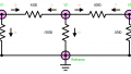
Then we have current regulator diodes. Current regulator diodes are designed to provide a relatively constant forward current over a wide range of voltages. This is kind of like what we did with a Zener. Remember a Zener provided a constant voltage over a wide range of voltages. But this is going to provide a constant current over a wide range of voltages. The diode functions as a constant current source. And the forward resistance of a current regulator diode is very high, somewhere in the vicinity of 250 k ohms to over 20 megohms.
If we look at the characteristic curve here we will note a very flat region here. This one is set up for three milliamps and you might note here this scale here … this is showing the diode current and this is showing the voltage and this scale is actually in milliamps. This device, if we look at the voltages that are being placed across it from here, we start at probably, I don't know, about four volts right here. And then all the way up to probably 110 volts. You'll notice that the current remains constant. And this is … the purpose of these diodes is to regulate current. And so across this wide variation of voltages, we see this constant current. Now the current is not constant down here. And this would be in the lower voltage reverse regions. And our concern is not there because our concern is a constant current device. And this is the symbol that you would see in a current regulator diode.
Step Recovery Diodes
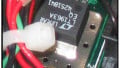
Then we have step recovery diodes. Step recovery diodes are characterized by extremely fast switching times. They are primarily used in communication circuits above one gigahertz. And so this makes them suitable for microwave use. And this is the symbol … it just looks like a regular symbol. And this is actually a picture of a step recovery diode. And you can have an idea of its size. It's relatively small.
Step recover diodes are doped differently than other types of diodes with less doping at the p-n junction than away from it. So there's going to be less doping at the junction than in the regions away from it. And this picture here kind of depicts that.
Tunnel Diodes
Then we have tunnel diodes. Tunnel diodes are another device designed to be operated at very high frequencies. And here is a symbol for one. And then these are some actual tunnel diodes courtesy of Atlantic Microwave. The p-n junction is doped much more heavily than other types of diodes. Tunnel diodes are used in the forward bias state and exhibit what is known as negative resistance. A portion of the characteristic curve actually has decreased current as voltage across it increases. And your text actually has a picture of this characteristic curve. And this is called negative resistance. And there's only a portion of the characteristic curve that does this. And this actually contradicts Ohm's Law. In Ohm's Law if you increase the voltage across a specific device the current through it increase as well. With these, there's a portion of the curve that exhibits this interesting property of negative resistance.
PIN Diodes
Then the final one we're going to look at is PIN diodes. PIN diodes are another device intended for use at extreme frequencies. We're talking about frequencies 100 megahertz to 100 gigahertz. A layer of p-type material is separated from a layer of n-type material by a layer of intrinsic or very lightly doped silicon. So in a PIN diode you'd have your p-material and then we would have the n-material and then in between here, we would have a piece of intrinsic semiconductor material … this is just basic semiconductor material … or it's extremely … it's very lightly doped. And the three layers are pictured in your text. The P, the I, the N gives rise to its name, the p-material, intrinsic and the n-type material.
Because of the intrinsic semiconductor material in between the p- and the n-material, the capacitance when reverse bias is extremely low. The NPN3404 … this is a Motorola PIN diode that's featured in your text. It has only 1.3 picofarads of capacitance over a wide range of reverse voltages. This makes it well suited for use at very high frequencies. The RF resistance can vary from less than one ohm with a high forward current to well over 1000 ohms for lesser currents. This makes them well suited to acting as … and this is an interesting device … as a current control resistance. So as current varies the resistance across this device will vary.
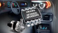
Partial Data Sheet for an NPN3404
This is a partial data sheet for an NPN3404. I've cut and pasted this from a data sheet I picked up on the internet. In fact, all of these devices we've been looking at … if you have a part number, if you go to Google, you can pick up the data sheets on these devices.
So very briefly, we looked at PIN diodes … gets their names from their unique construction. We looked at tunnel diodes. They exhibit a property called negative resistance. We looked at step recovery diodes. These are very high-frequency devices suitable for microwave use. We looked at current regulator diodes. These are diodes that have a characteristic kind of similar to Zeners in that they maintain a constant current over a wide variety of input voltages. We looked at the Schottky diode which is optimized to eliminate capacitance and for use at very high frequency. And finally, Varactor diodes is where we started. And these are actually used as a variable capacitance.